

C Profile Systems: Selection and Installation Guide
A support route can look simple on a drawing, yet its performance depends on many connected decisions: profile geometry, steel thickness, finish, slot pattern, brackets, rods, anchors, and installation quality. This guide explains how to select and install C profile systems methodically, without relying on assumptions that may not fit your project.
You will learn how common profile options differ, what to review before ordering, how to plan a coordinated installation, and which checks belong in final inspection. The practical example uses Ardıç’s AC-41-41-25-3 PG profile, while the selection process applies across the broader range.
What Is a C Profile System?
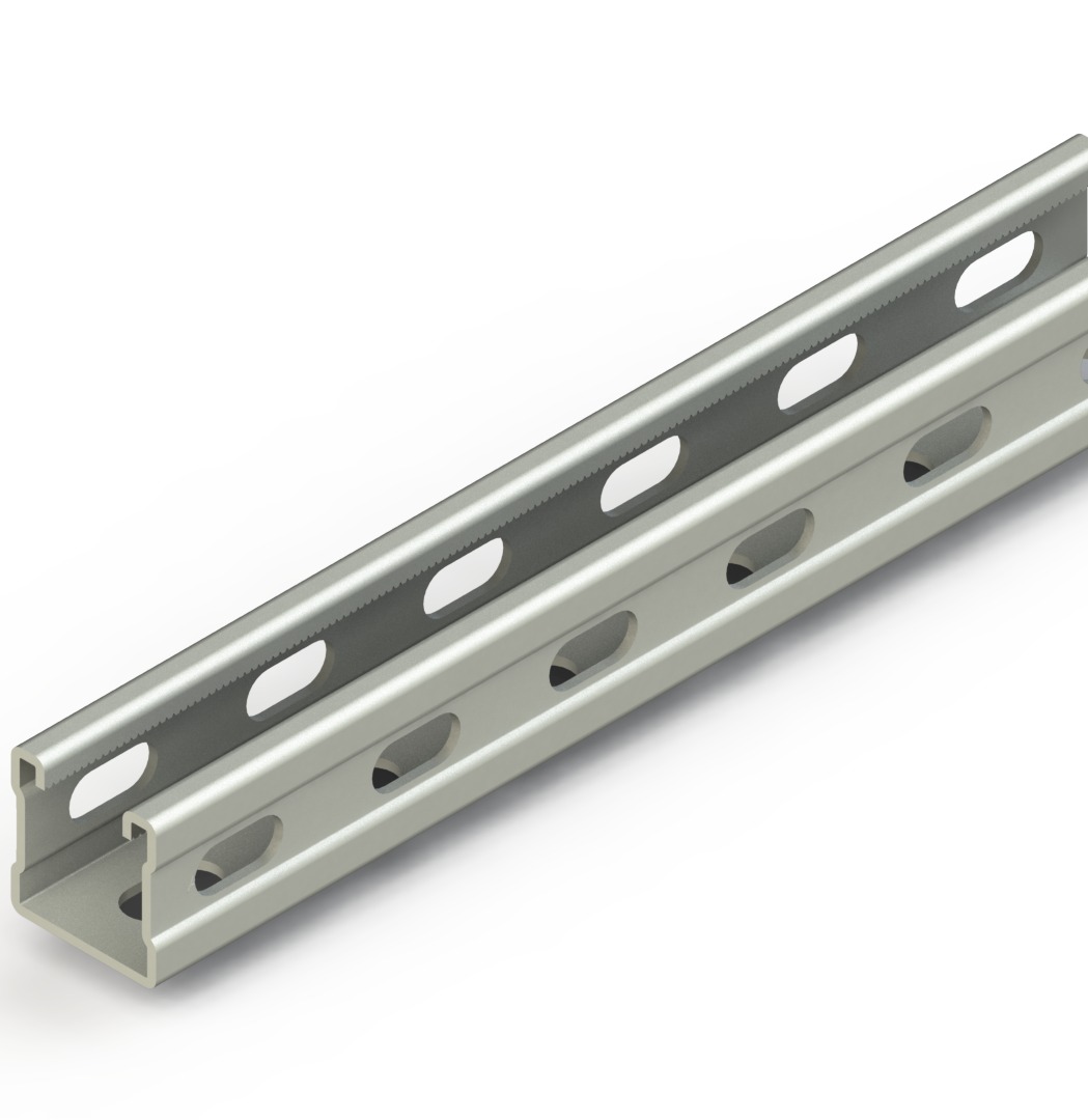
A C profile is a formed steel channel with an open face. Compatible channel nuts, brackets, and fasteners can connect to that face, allowing installers to build adjustable support frames without welding every joint. Perforated faces can also provide repeatable connection points for attachments.
The profile is only one part of the system. A working assembly may include wall brackets, base plates, threaded rods, hangers, channel nuts, bolts, anchors, and cable-support components. Treating these parts as one coordinated system helps avoid mismatched geometry or finishes.
C profiles are valued for modularity. Routes can be aligned, attachments repositioned, and assemblies adapted around site constraints. However, modular does not mean universal: the correct profile and connection arrangement must follow project loads, support spacing, substrate conditions, environmental exposure, and the current manufacturer data.
Where C Profiles Fit in Building Services
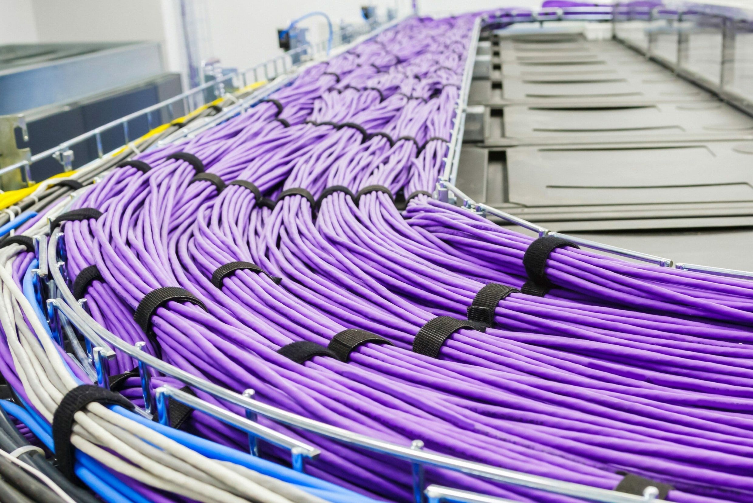
C profile systems can create support points on walls or suspended frames. Ardıç’s product information identifies use with hangers or wall attachment, brackets, threaded rods, and cable-support systems for lighting routes. These applications show the system’s role as an adaptable interface between the building structure and supported services.
Typical configurations include single suspended channels, wall-mounted cantilever arrangements, trapeze-style frames, and multi-level service supports. The appropriate configuration depends on the route, access needs, and approved project design. A profile suited to a compact branch route may not suit a heavily populated shared-services corridor.
Coordination matters before installation starts. Check proposed supports against ducts, pipes, cable trays, luminaires, access panels, fire stopping, and maintenance zones. Early coordination can prevent unnecessary offsets and avoid placing a support where future equipment access is required.
Understanding Sizes, Thicknesses, Slots, and Finishes
The Ardıç C profile category presents several selection variables. Listed sizes include 41 × 21, 41 × 41, 62 × 41, 41 × 42, and 41 × 82 mm. Available thickness filters include 1.2, 1.5, 2.0, and 2.5 mm, while slot options include one-slot and three-slot formats.
Dimensions affect assembly depth, connection geometry, and the space available around supported services. Steel thickness is another important design input, but it cannot be converted into a safe load by rule of thumb. Capacity also depends on profile orientation, span, restraints, connection details, and the load case.
Slot configuration can influence where accessories connect and how easily an installer can align an assembly. Confirm that the specified brackets and fasteners suit the chosen perforation pattern. Do not assume accessories from unrelated systems are interchangeable because their nominal dimensions look similar.
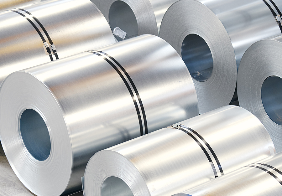
Finish options shown for the series include PG and HDG, while the relevant product card also mentions SS. PG refers to pre-galvanized steel; HDG refers to hot-dip galvanized material or treatment, depending on the product specification; SS denotes stainless steel. Select the finish through an exposure and project-specification review, not by appearance alone.
Product Example: AC-41-41-25-3 PG
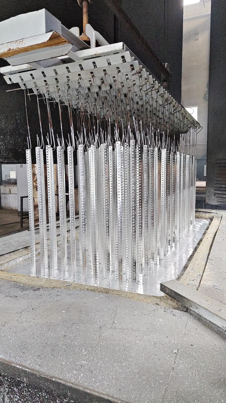
The exact AC-41-41-25-3 PG C profile is a clear example of how a product code describes a configuration. The verified item has a 41 × 41 mm section, 2.5 mm steel thickness, a standard length of 3000 mm, three perforated or slotted faces, and a PG pre-galvanized finish.
| Attribute | Verified product detail |
|---|---|
| Product code | AC-41-41-25-3 PG |
| Section | 41 × 41 mm |
| Steel thickness | 2.5 mm |
| Standard length | 3000 mm |
| Face format | Three-slot / perforated faces |
| Finish | PG / pre-galvanized |
These facts identify the item; they do not establish a project-specific load rating, allowable span, anchor capacity, or connection torque. Obtain the current datasheet and complete the required engineering calculations before structural or load-bearing selection.
C Profile Selection Guide
A good selection process starts with the application rather than a familiar catalogue code. Record the supported systems, route geometry, operating environment, access constraints, and interfaces with the building. Then compare compliant options using current product documents.
- Define the loads. Include the supported equipment and service loads, connection layout, and project-required load cases. Allowances or dynamic effects must come from the responsible design basis, not a generic percentage.
- Establish the support arrangement. Determine whether the design uses wall attachment, suspension by threaded rods, a frame, or another approved configuration. Note orientation, restraint, and proposed support spacing.
- Review section and thickness. Compare candidate dimensions and steel thicknesses against project calculations and the current datasheet. A deeper or thicker profile is not a substitute for checking the complete assembly.
- Select the face pattern. Choose one-slot or three-slot geometry according to connection positions, accessory compatibility, and installation access.
- Choose the finish. Match PG, HDG, or SS options to the specified environment, corrosion strategy, and material compatibility. Review cut edges and site modifications under the approved procedure.
- Verify every interface. Confirm channel nuts, brackets, rods, bolts, anchors, and supported-system attachments are compatible and documented for the intended arrangement.
- Close the documentation loop. Check product code, length, quantity, finish, revision, and required certificates or records before procurement.
Plan the Complete Support Assembly
Ordering profiles before detailing the connections can delay installation. Build a bill of materials for each support type, including profiles, brackets, channel nuts, bolts, washers, threaded rods, hangers, anchors, end protection, and any interface component required by the supported system.
Check connection access in the model or drawing. Installers need enough room to insert and position nuts, fit tools, and inspect the completed connection. Congested assemblies may look feasible in plan view but become difficult to tighten or verify on site.
Material compatibility deserves attention. Mixing finishes or metals can affect the corrosion strategy, especially where moisture or contaminants are present. Follow the project specification and manufacturer guidance for compatible components, isolating materials where the approved design requires it.
Also standardize support types where practical. A controlled set of approved details simplifies ordering, installation briefings, and inspection. Any site-driven deviation should enter the project’s technical approval process before work proceeds.
Step-by-Step C Profile Installation Guide
Installation should follow approved drawings, method statements, risk controls, and manufacturer instructions. The sequence below provides a coordination framework; it does not replace project-specific engineering or safety documentation.
- Confirm the latest documents. Verify drawing revision, support detail, product code, finish, and component schedule. Resolve discrepancies before marking or cutting.
- Inspect delivered materials. Check dimensions, labels, straightness, perforations, finish, and transport damage. Segregate questionable components rather than installing them.
- Survey and mark the route. Transfer approved levels and support positions accurately. Confirm clearances from other services, openings, and maintenance areas.
- Verify the substrate and anchors. Confirm that the actual base material matches the approved anchor design. Edge distances, embedment, drilling, cleaning, and installation must follow the specified anchor procedure.
- Measure and cut safely. Use an approved cutting method, control sharp edges and debris, and protect the finish or cut edge as required by the specification. Do not introduce unapproved holes or heat damage.
- Preassemble where suitable. Fit brackets and channel accessories in a controlled area when this improves accuracy. Keep connections adjustable until alignment is confirmed.
- Install and align supports. Position wall or suspended assemblies to the approved line and level. Prevent profile twist, unintended eccentricity, and rod misalignment.
- Complete connections. Tighten specified fasteners using the current product and project requirements. Never infer torque from bolt size alone.
- Attach services without overloading. Follow the planned loading sequence and keep temporary construction loads off the assembly unless approved.
- Inspect and record. Check geometry, connection engagement, anchors, finish, labels, and deviations. Close inspection points before access is covered.
Quality, Safety, and Common Mistakes
Common problems often begin before the first profile is fixed. Substituting a different thickness, finish, slot pattern, or accessory without review can change the documented assembly. A visually similar component is not automatically equivalent.
- Do not select profile capacity from dimensions alone.
- Do not exceed a span copied from another project or support type.
- Do not drill the structure until the anchor location and substrate are approved.
- Do not mix accessories without confirming fit and system compatibility.
- Do not leave cut edges, burrs, or damaged coatings untreated where protection is required.
- Do not conceal connections before required inspection records are complete.
Safe work also requires task-specific controls for lifting, cutting, drilling, work at height, sharp edges, and falling objects. The responsible contractor should define those controls through the site risk assessment and method statement. Product selection alone cannot manage installation risk.
Inspection and Maintenance
Support systems should remain accessible enough for the inspections required by the facility plan. Review visible deformation, loose or missing components, coating damage, corrosion, anchor-zone distress, and unauthorised additions. Changes to supported routes can alter the original load and should trigger technical review.
Record the support type, location, product identification, installation date, inspection status, and approved deviations. Good records help maintenance teams distinguish an original design condition from a later modification. They also support traceability when components need replacement.
If an inspection identifies damage or movement, isolate the area as the site procedure requires and obtain competent assessment. Do not straighten, weld, reinforce, or add supports without an approved repair detail.
Frequently Asked Questions
Concise answers to practical questions about C profile selection and installation.
Specify the Right C Profile System
Review the application, product configuration, finish, and connection requirements with the Ardıç team before procurement.
Contact Ardıç