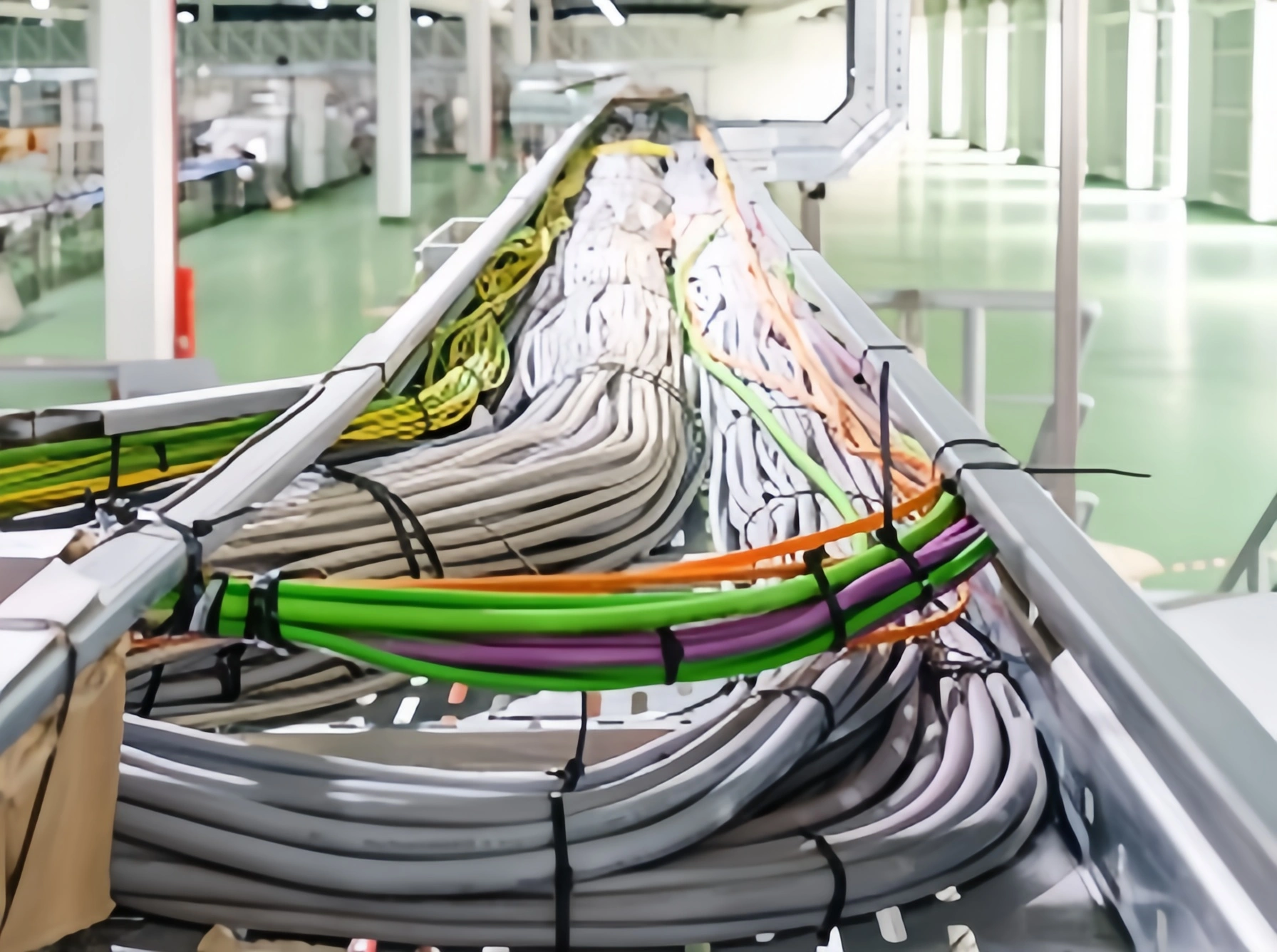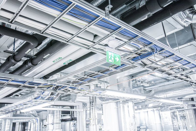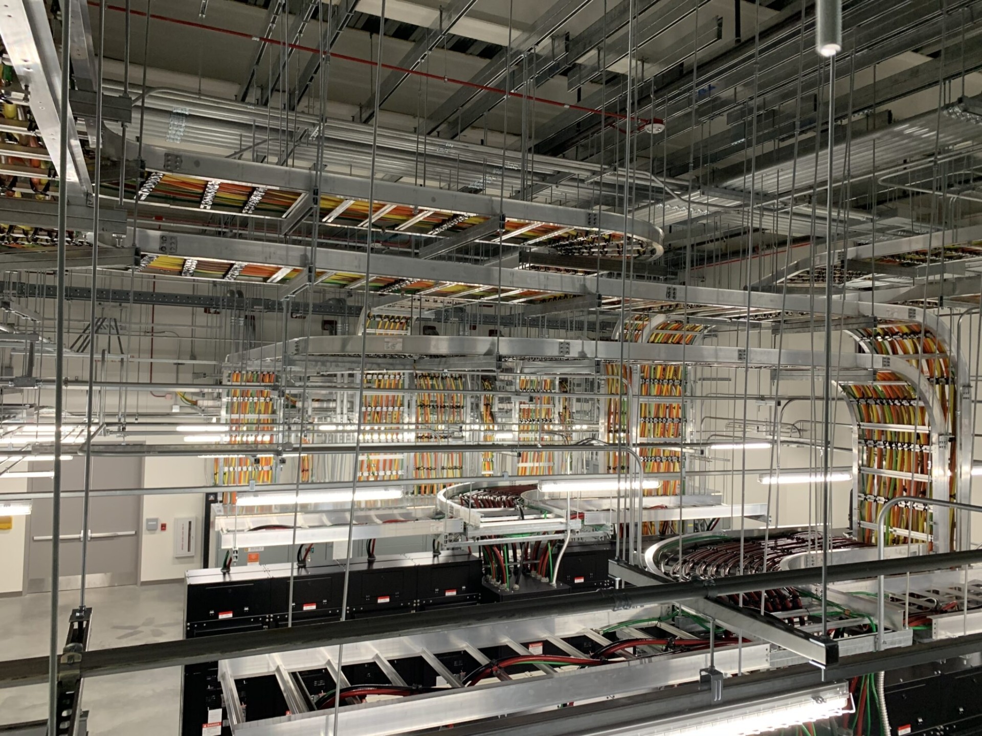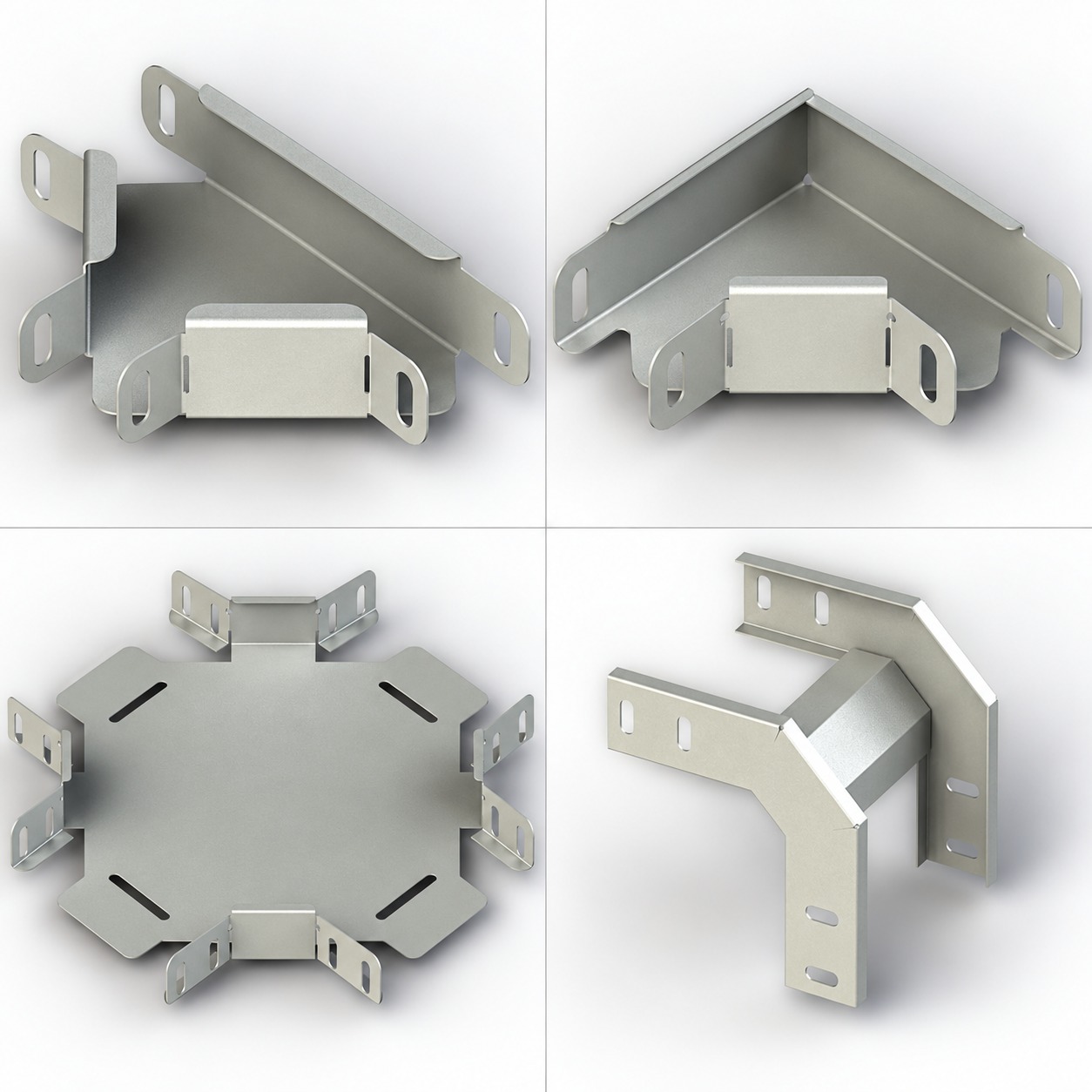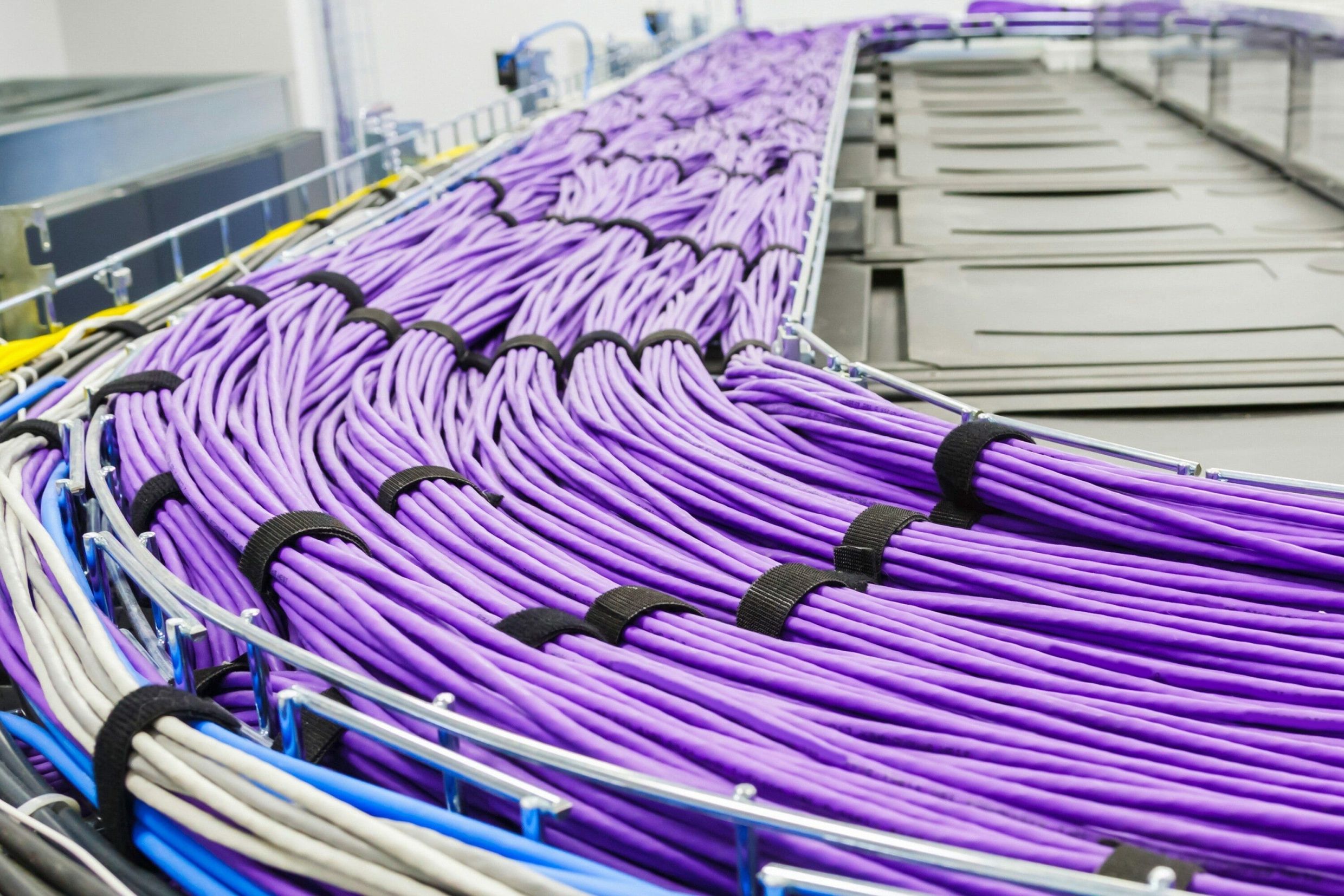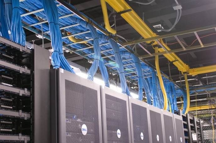


Types of Cable Tray: Perforated, Solid, Ladder and Wire Mesh
Choosing among the types of cable tray requires more than naming a universal winner. The right family depends on the cables, route, environment, thermal limits, loads, supports, and access. A cover changes ventilation and access.
This guide compares perforated, solid-bottom, ladder, and wire-mesh systems without assigning generic capacity or compliance. Shortlist candidates, then verify the configuration against project rules, cable instructions, and manufacturer data.
Table of contents
- Start with the system, not the shape
- Perforated cable tray
- Solid-bottom cable tray
- Cable ladder
- Wire-mesh cable tray
- Conditional cable tray selection matrix
- Checks shared by every tray family
- A practical selection workflow
- Common selection mistakes
- Frequently asked questions
- Conclusion
Start with the system, not the shape
A cable tray is a mechanical support system, not simply a container. NEMA describes rigid structural systems for cables, raceways, and insulated conductors, including ladder, trough, channel, and wire-mesh forms.[2] IEC 61537:2023 covers requirements and tests for systems that support and accommodate cables.[1]
Selection involves more than the bottom pattern. A route includes straights, fittings, couplers, supports, covers, dividers, fasteners, bonding provisions, drop-outs, and equipment interfaces. One unsuitable detail can govern the route.
Separate three decisions from the outset:
- System family: perforated, solid-bottom, ladder, or wire mesh.
- Construction: material, finish, geometry, dimensions, fittings, and accessories.
- Engineering basis: cable schedule, loading, span, environment, electrical rules, and maintenance needs.
A category page can help you explore cable tray options, but it does not by itself prove capacity, suitability, or standards compliance for a project.
Perforated cable tray
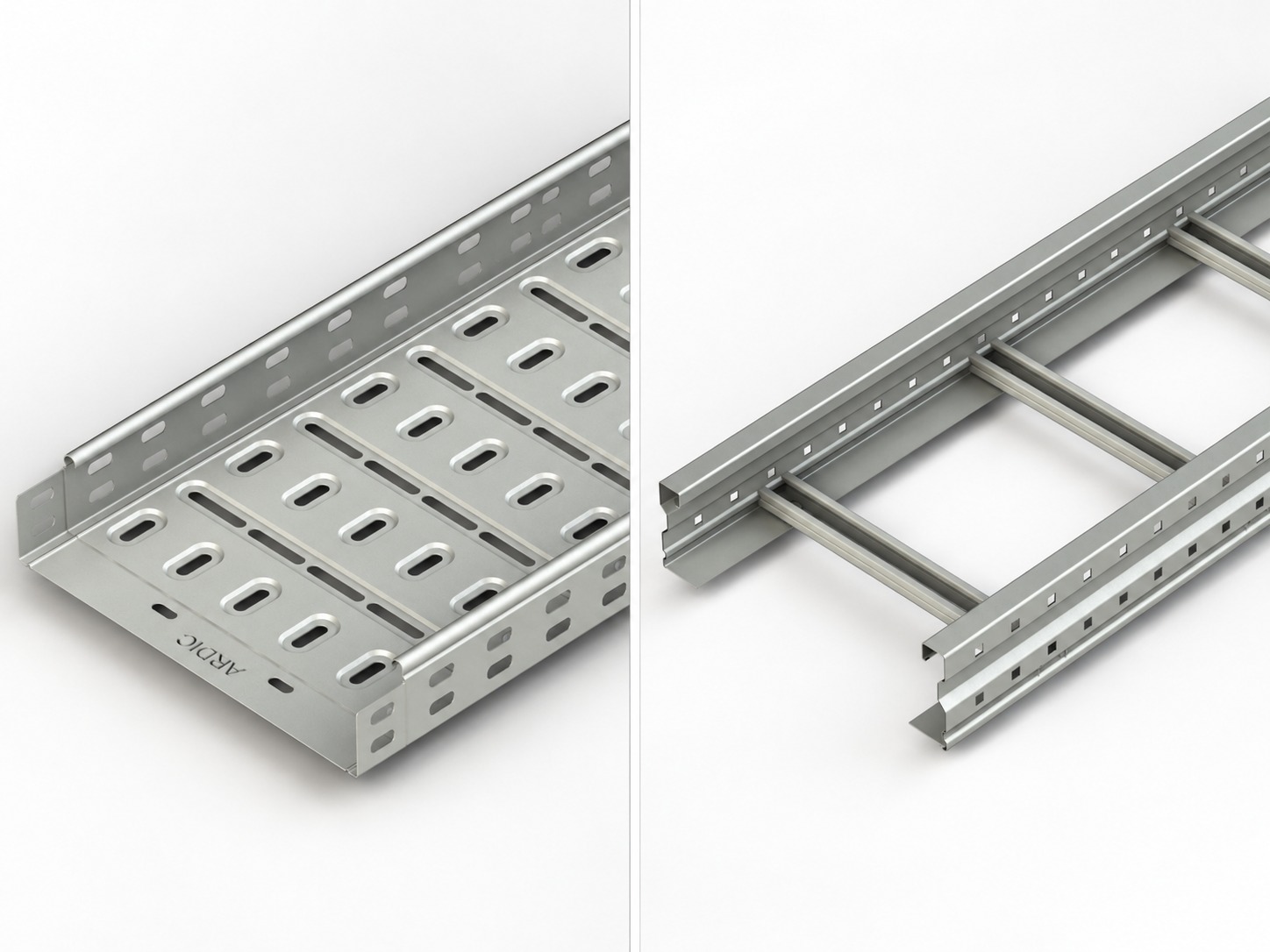
A perforated cable tray has a bottom with intentionally placed openings. Eaton’s pan-tray catalogue identifies perforated-bottom sections and notes that slot patterns vary by tray size and type.[8]
Perforated tray can balance underside support and openness. Suitability depends on opening pattern, edge treatment, permitted support distance, and bend radius.
Do not convert “perforated” into a thermal guarantee. Ampacity depends on applicable rules, cable construction, loading, ambient conditions, spacing, and installation arrangement. Covers, dense bundles, dividers, and debris can change thermal conditions.
Openings may help drainage, but they do not establish weather protection or prevent deposits. Check orientation, cleaning, corrosion, and possible water paths into nearby equipment.
Before selecting perforated tray, confirm:
- cable outside diameters and allowable support conditions;
- required bend radii at bends, tees, risers, and exits;
- permitted cable grouping, segregation, and ampacity basis;
- cleaning access and the likelihood of dust, water, or process residue; and
- verified load data for the exact tray, span, joints, and support arrangement.
Solid-bottom cable tray
A solid-bottom cable tray provides continuous support without intentional bottom openings. Consider it when cables need continuous bearing, openings are undesirable, or a coordinated metallic enclosure contributes to an EMI/RFI strategy.
The Cable Tray Institute describes solid-bottom steel tray with steel covers as a possible shielding approach when the completed installation avoids breaks and holes.[3] This does not prove that any generic tray achieves a required shielding value. Joints, covers, penetrations, bonding, material, frequency, and the complete EMC design remain relevant.
A solid bottom can retain moisture. Eaton’s guide recommends drainage measures for defined conditions when shielding is not required.[4] This is manufacturer-specific guidance, not permission to drill trays. Field holes may affect corrosion protection, structure, warranties, bonding, or shielding.
Solid construction can reduce airflow compared with an open arrangement, so cable sizing and ampacity methods must match the installation. A cover further changes heat transfer, access, loading, and inspection visibility.
Consider solid-bottom tray only after answering these questions:
- Is continuous cable support genuinely required?
- What contamination or mechanical exposure must be controlled?
- Can water enter, condense, and drain safely?
- Is EMI/EMC performance required, and how will it be verified as a system?
- How will installers add, inspect, clean, and remove cables?
Cable ladder
A cable ladder uses side rails joined by transverse rungs. Its open construction permits airflow and cable entry above or below the route. Rungs provide restraint points. Eaton also directs designers to respect cable-maker bend-radius limits.[4]
Ladder is a frequent candidate for power and industrial routes, but it is not “heavy duty” by definition. Rail profile, rungs, width, material, joints, span, fittings, and load all influence performance.
Rung spacing must suit the cables. Small cables may sag or exceed permitted unsupported distances. Large-cable exits must not force bends tighter than cable instructions allow. Do not modify rungs without approval.
Open construction improves visibility but exposes cables to the environment. Assess falling objects, sunlight, deposits, water, ice, contact, and maintenance. A cover cannot replace environmental, thermal, or mechanical design.
Use the cable ladder overview to identify relevant configurations, then request exact load, deflection, fitting, joint, and support data for the selected system.
Wire-mesh cable tray
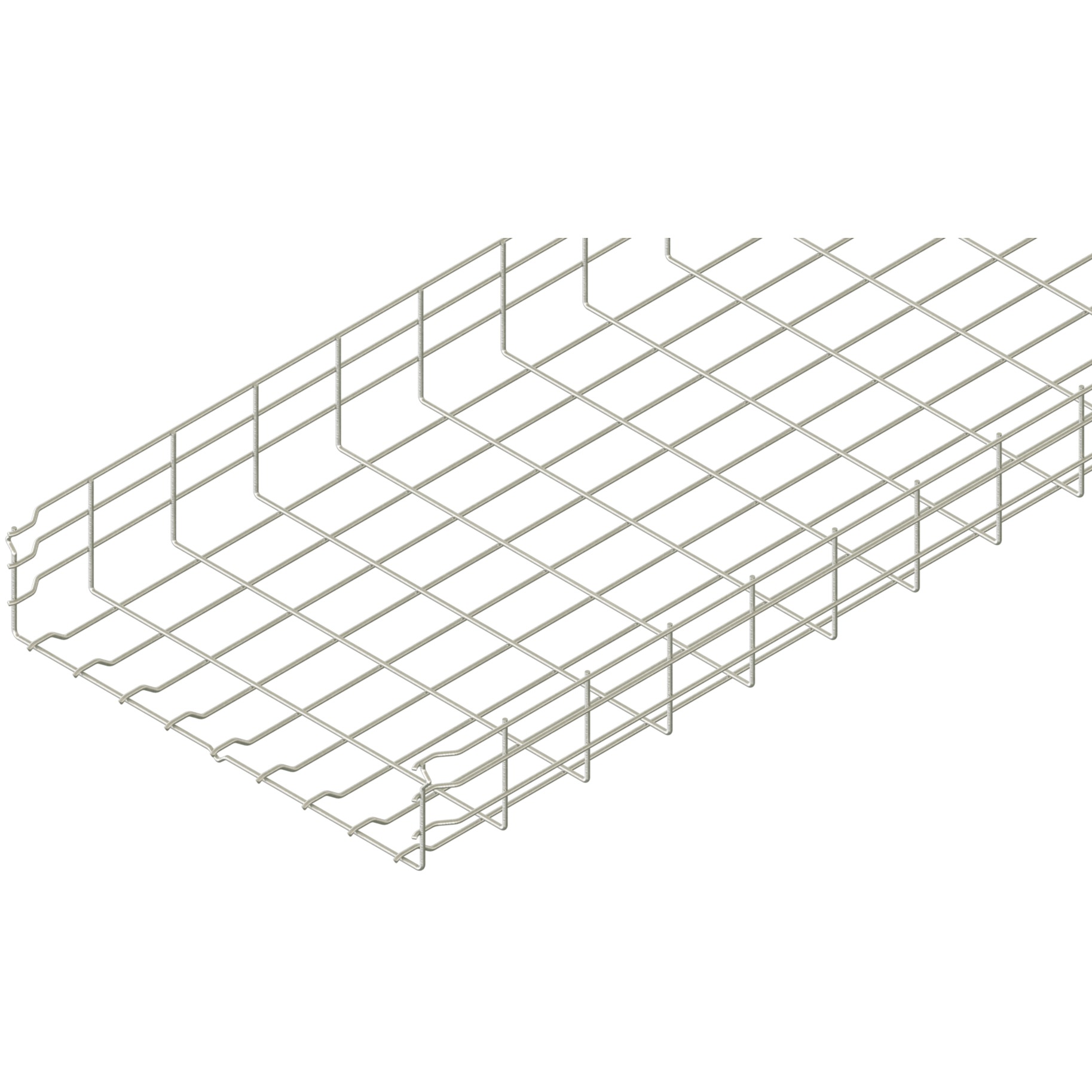
A wire-mesh cable tray, often called wire basket, uses a wire grid. NEMA includes metal wire mesh/basket among cable tray types.[2]
Eaton defines its Flextray system to include continuous wire mesh, field-formed bends, tees, drop-outs, supports, and accessories. Its specification requires field forming to follow the manufacturer’s instructions.[7] Legrand likewise documents on-site fabrication of turns, bends, and elevation changes for its Cablofil wire-mesh system, plus dedicated drop-out accessories.[9][10] These manufacturer-specific examples support considering wire mesh for route changes only when the selected product documents permit them.
Verify that grid and exit details suit every cable. Check cable-maker limits for support, pulling tension, crushing, bend radius, and ties.
Wire diameter, grid geometry, depth, width, material, couplers, supports, and span can change load and deflection. Do not transfer values from a similar-looking basket. Coordinate the selected wire-mesh system with approved accessories and current documents.
Grounding and bonding need project-specific design. Eaton’s specification separately requires continuity between components and bonding or grounding under the applicable rules for its system.[7] Open geometry alone proves neither continuity nor compliance.
Conditional cable tray selection matrix
Use this matrix as a preliminary shortlist, not a final specification. “Consider” means the family may address the stated condition if the exact system, cables, and project checks support it.
| Project condition | Perforated | Solid bottom | Ladder | Wire mesh | Verification before selection |
|---|---|---|---|---|---|
| Small cables need frequent underside support | Consider | Consider | Check rung spacing | Check grid and added support | Cable-maker support and deformation limits |
| Heat dissipation is a priority | Consider open arrangement | Requires detailed thermal review | Consider open arrangement | Consider open arrangement | Ampacity method, grouping, ambient temperature, covers |
| Large power cables and controlled exits | Check base openings and fittings | Check thermal and exit details | Consider with suitable rungs and radii | Product-specific review | Cable weight, restraint, bend radius, fault forces |
| Frequent field route changes | Use documented fittings | Use documented fittings | Use documented fittings | Consider approved field forming and drop-outs[7][9][10] | Instructions, edge treatment, fittings, support locations |
| Water or condensation is credible | Verify drainage path | Resolve retention and drainage | Open bottom may help | Open grid may help | Equipment below, corrosion, orientation, ingress source |
| Dust or process residue is credible | Assess deposits and cleaning | May limit underside exposure but can retain deposits | Assess cable exposure | Assess cable exposure | Cleaning method, covers, ventilation, hazardous-area rules |
| EMI/EMC shielding objective | System-level assessment | Consider coordinated metal tray and cover | Usually needs another strategy | Usually needs another strategy | Shielding target, joints, bonding, penetrations, testing |
| High-change communication route | Consider | Access may be less convenient | Consider cable support details | Consider | Moves/adds plan, bend control, segregation, capacity |
| Long or demanding support spans | Product-specific | Product-specific | Product-specific | Product-specific | SWL, deflection, joints, fittings, supports, environmental loads |
The matrix deliberately avoids universal winners. One project may use several families: ladder on a power backbone, perforated tray for controls, and wire mesh near communication equipment. Interfaces between systems then require the same attention as each straight run.
Checks shared by every tray family
Tray type does not settle the following engineering topics:
- Capacity and supports: obtain manufacturer load and deflection data for the exact configuration and proposed spacing. Verify brackets, channels, rods, anchors, fasteners, and the supporting structure. Review supporting-system categories only as a coordination starting point.
- Bend radius and cable support: check every horizontal bend, vertical bend, tee, reducer, dropout, and transition against cable instructions.
- Fill, ampacity, and segregation: apply the current electrical rules for the jurisdiction and the selected cable types. Ventilation alone does not establish allowable fill or current rating.
- Grounding and bonding: design continuity, bonding jumpers, connections, and any protective-conductor function under applicable rules and verified product documentation.
- Fire performance: coordinate cable fire properties, penetrations, firestopping, supports, and circuit-survival requirements. Tray material or shape alone does not establish a fire rating.
- Environment: assess corrosion, chemicals, ultraviolet exposure, temperature, water, ice, wind, seismic actions, vibration, and physical impact.
- Maintenance: provide safe access for inspection, cleaning, cable changes, and removal of abandoned cables.
OSHA’s advisory bulletin emphasizes proper installation, maintenance, inspection, support, loading, and grounding, while noting that its bulletin creates no new legal obligations.[6] NEMA’s current BI 50016-2024 installation guide likewise covers installation, maintenance, and system modification.[5] Always apply the rules governing the actual project location.
A practical selection workflow
- Classify the cables. Record cable type, diameter, mass, voltage or service, thermal data, bend radius, pulling limits, and special support instructions.
- Divide the route into conditions. Mark indoor and outdoor sections, wet or dusty zones, hazardous areas, vertical runs, crossings, penetrations, and equipment approaches.
- Set performance needs. Define loads, future capacity, deflection criteria, access, segregation, EMC objectives, fire strategy, corrosion exposure, and cleaning method.
- Shortlist tray families. Use the matrix to identify candidates without declaring a final winner.
- Develop the route. Select documented bends, tees, reducers, risers, covers, dividers, couplers, drop-outs, and transitions.
- Verify exact product data. Match material, finish, dimensions, span, joints, orientation, fittings, and support arrangement to current manufacturer documents.
- Coordinate electrical and structural rules. Check fill, ampacity, segregation, bonding, fault restraint, environmental actions, and the complete load path.
- Review installation and maintenance. Confirm access, lifting, cutting, edge treatment, cable placement, inspection, cleaning, and future modifications.
- Record the basis. Put product references, document revisions, assumptions, exceptions, and required inspections in the submittal and drawings.
Common selection mistakes
Choosing by cable label alone. “Power,” “data,” or “control” does not capture weight, heat, radius, segregation, or environment.
Treating a cover as universal protection. Covers change exposure, airflow, loading, access, and water behaviour. Give each cover a defined purpose.
Assuming openness solves heat. Ampacity depends on the complete cable and installation arrangement, not only the tray family.
Copying a capacity or support span. Ratings belong to exact products and configurations. Similar appearance is not evidence.
Ignoring fittings and interfaces. Straight sections may pass while bends, drops, couplers, brackets, or field transitions remain unresolved.
Using standards as product certificates. A standards page defines scope or requirements; it does not prove that an unspecified product complies.
Frequently asked questions
There is no universally best type. Select conditionally from the cable requirements, thermal design, route geometry, environment, loading, supports, access, and maintenance plan, then verify the exact system.
Perforated tray has openings in its bottom, while solid-bottom tray provides a continuous surface. The difference affects ventilation, drainage, cable support, contamination behaviour, inspection, and potential EMC strategies, but suitability remains project-specific.
No. Ladder can support different permitted cable services when the rung spacing, restraint, bend radius, loading, segregation, and applicable installation rules are satisfied. Cable type and project requirements control the decision.
It can be a candidate when its documented grid, exits, and route-forming methods match the communication cables. Eaton documents field-formed bends, tees, and drop-outs for its Flextray system, while Legrand documents on-site route changes and wire-mesh drop-out accessories for Cablofil; neither permission transfers to another system.[7][9][10] Verify cable support, bend and crush limits, ties, loading, span, segregation, and bonding.
Not automatically. A cover may reduce specific exposures, but joints, edges, wind restraint, drainage, condensation, corrosion, cable temperature, access, and the surrounding installation still require engineering review.
Conclusion
Solid-bottom tray offers continuous support but needs careful thermal, drainage, and access review. Ladder and wire mesh provide open pathways, yet their support, fittings, and exposure require verification.
For project-specific product coordination, send the cable schedule, route drawings, environment, loading basis, support concept, and required documentation through ARDIC’s contact page.
A defensible selection records why a family fits each route condition and proves the final configuration with current project and manufacturer evidence.
Sources
[3] Cable Tray Type Selection — Cable Tray Institute
[4] Cable Tray Design Considerations — Eaton
[5] NEMA BI 50016-2024 (VE2) — NEMA
[6] Safely Installing, Maintaining and Inspecting Cable Trays — OSHA
[7] Flextray Wire Basket Cable Tray Specification — Eaton
[8] B-Line Series Pan Tray Catalog — Eaton