

Cable Management Systems for Data Centers
Data center cable management systems are the physical pathway, access, identification, and change-control layer that helps teams work around live equipment. This coordination-first guide covers route zoning, pathways, cabinet transitions, labels, records, and controlled change without assigning universal engineering values or performance outcomes.
- [What a cable management system covers](#what-a-cable-management-system-covers)
- [Start with route zoning and coordination](#start-with-route-zoning-and-coordination)
- [Choose pathways as a coordinated system](#choose-pathways-as-a-coordinated-system)
- [Plan cabinet entries, transitions, and service access](#plan-cabinet-entries,-transitions,-and-service-access)
- [Keep segregation and bonding in their proper scope](#keep-segregation-and-bonding-in-their-proper-scope)
- [Make identification and documentation operational](#make-identification-and-documentation-operational)
- [Manage change through the full lifecycle](#manage-change-through-the-full-lifecycle)
- [A practical review checklist](#a-practical-review-checklist)
- [Frequently asked questions](#frequently-asked-questions)
What a cable management system covers
Data center cable management systems are not a cosmetic finishing task. They are the physical pathway, access, identification, and change-control layer that helps teams work around live equipment without turning every move into a tracing exercise. A useful plan connects routes, cabinets, pathways, labels, records, and maintenance access before installation begins.
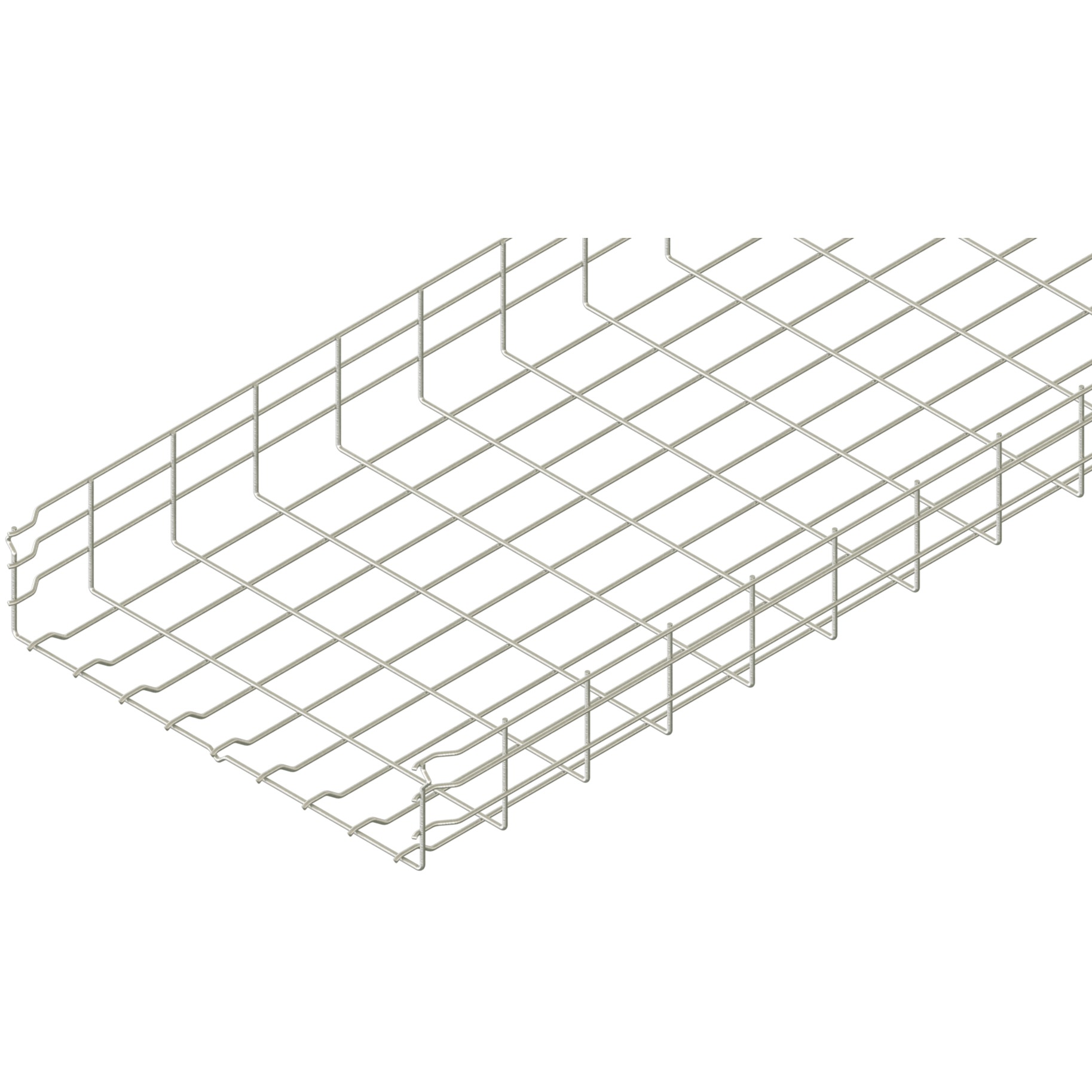
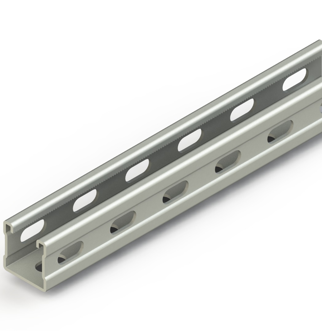
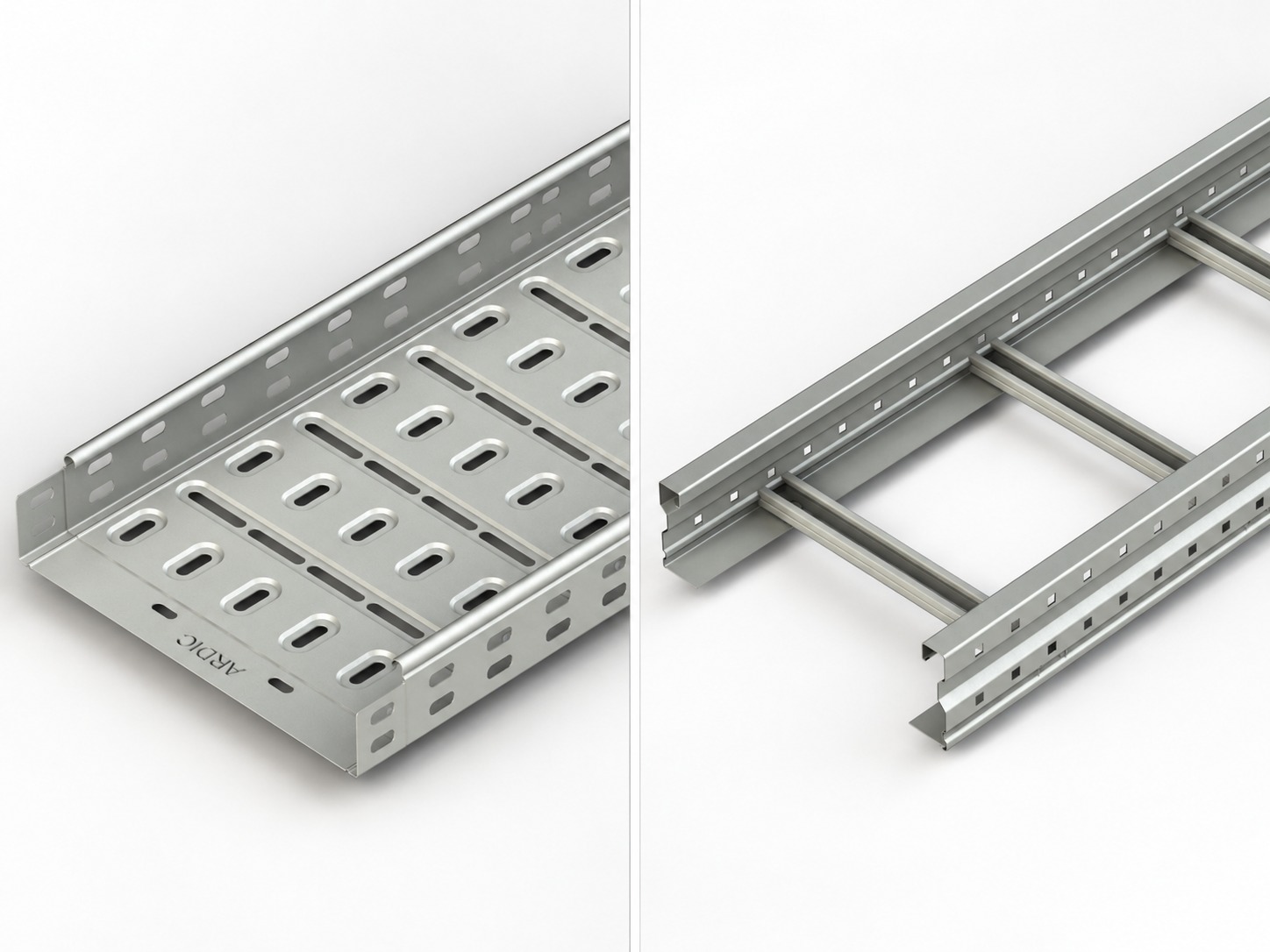
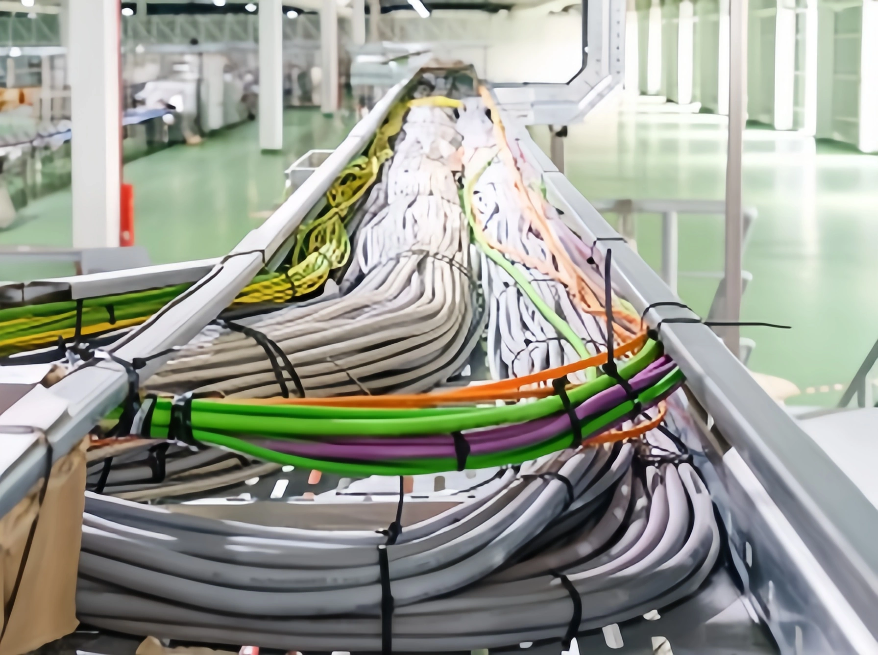
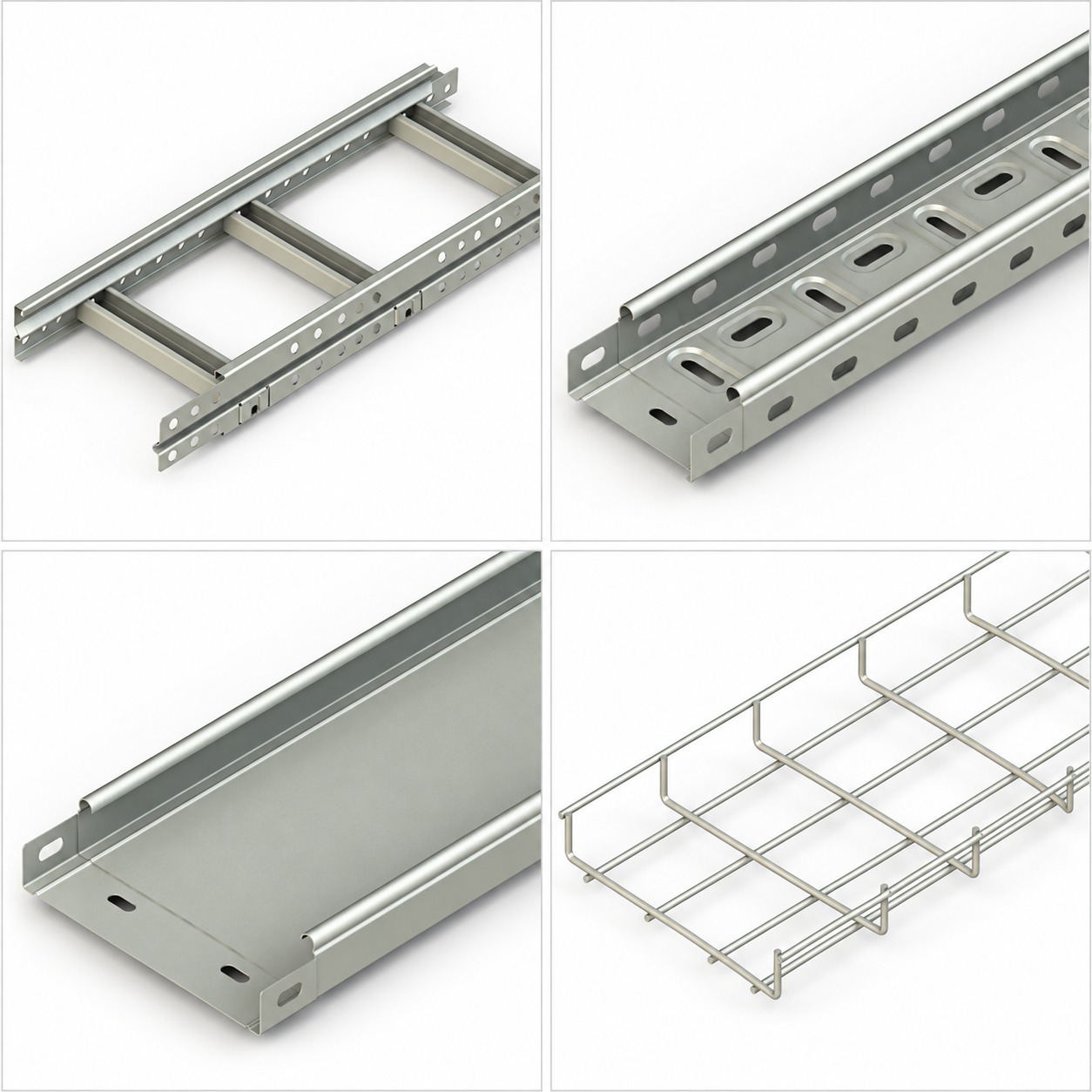
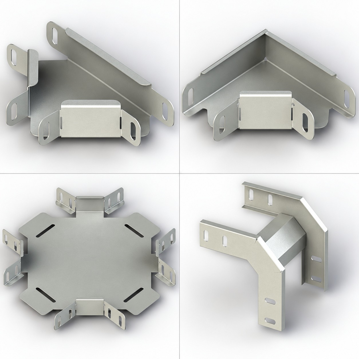
A cable management system can include trays, ladders, wire-mesh pathways, raceways, fittings, supports, cabinet managers, entry hardware, fasteners, labels, and records. Containment is only one part of the result. A neat tray does not establish electrical distribution, network performance, airflow, fire protection, seismic design, grounding, or availability; each has a separate design basis and review.
Begin by identifying the spaces and interfaces: entrance or distribution areas, equipment rows, cabinets, utility rooms, risers, and penetrations. Mark horizontal routes, vertical drops, and transitions. Then identify who owns each interface. The pathway plan should expose interfaces with electrical, network, mechanical, fire-protection, and structural work rather than claiming to replace it.
Start with route zoning and coordination
Route zoning gives every cable family a planned place before crews begin pulling cable. Establish primary routes between rooms or row zones, secondary routes serving cabinet groups, and cabinet-level routes. Keep route names simple enough that construction, operations, and commissioning teams use the same vocabulary.
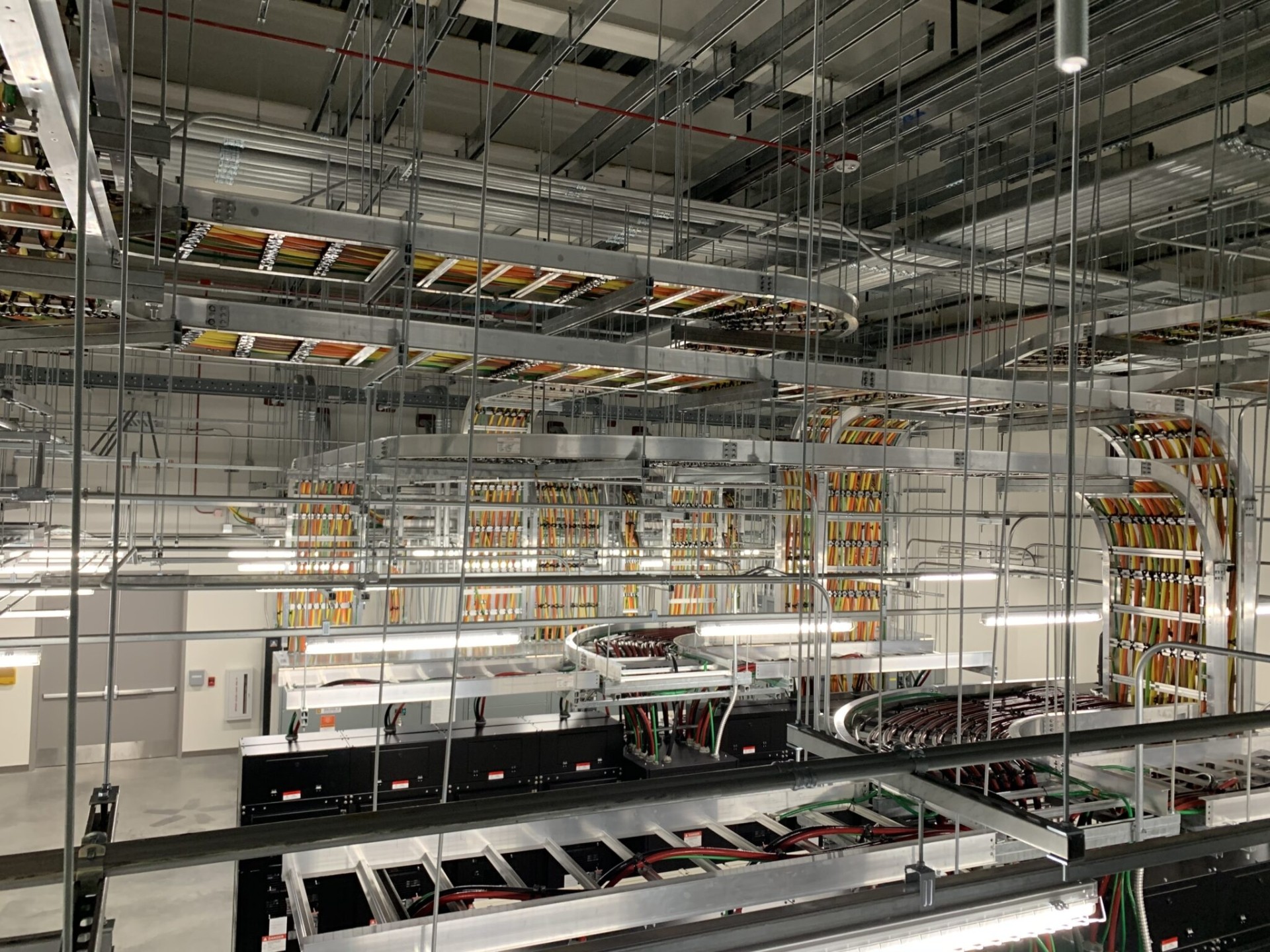
Use a current coordinated plan. Place cabinets, major equipment, doors, service clearances, ceiling obstructions, floor openings, cooling features, power infrastructure, fire-protection elements, and planned routes together. Review crossings and elevation changes early, because a route that looks clear in a two-dimensional plan may conflict in the field.
For each route, record cable families, installation sequence, access side, transition method, and design owner. Note where cables enter or leave a zone and where future changes can occur without disturbing unrelated services. ASHRAE notes that overhead power, cable tray, and lighting can make vertical space congested and recommends three-dimensional coordination for overhead infrastructure.[1]
Choose pathways as a coordinated system
Select pathways by function and interface, not by a product label alone. Open cable-support systems, enclosed raceway, and cabinet-level managers can all have a role. Review cable type, manufacturer instructions, environmental conditions, physical protection needs, support requirements, installation method, and access plan together.
Use the project cable schedule and route drawings for every segment. A backbone route can have different handling and transition needs from a short cabinet connection. Fiber, power, control, and communications services may need different arrangements. Confirm the required arrangement through the governing design documents and qualified review instead of importing a generic segregation rule.
Leviton’s fiber-raceway guide begins planning with cabinet and rack placement, ceiling height, HVAC restrictions, cable volume, transitions, and mounting needs.[3] These are useful coordination inputs, but product-specific support guidance cannot substitute for the design of another system.
For category context, review Ardıç Elektrik’s cable trays, cable ladders, and supporting systems alongside the project specification. These pages help identify categories; they are not compliance evidence or proof of data-center suitability.
Plan cabinet entries, transitions, and service access
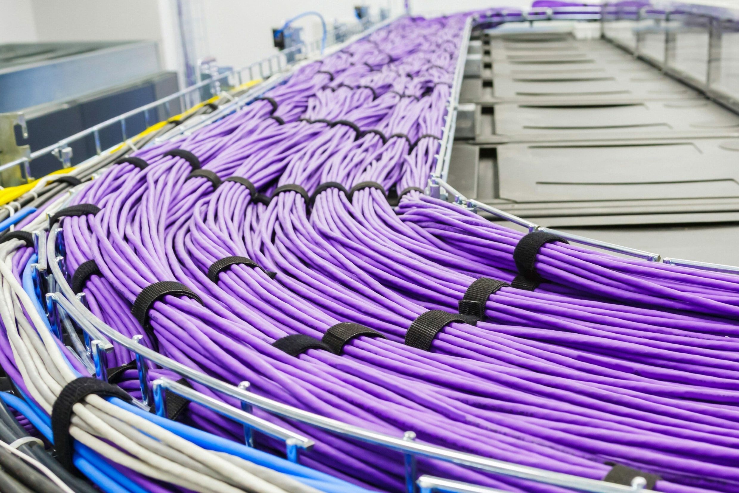
The route becomes operational at cabinet entry. Show where a pathway transitions to vertical management, patching hardware, or equipment ports. Include entry direction, work area, management hardware, and access needed for ordinary service. This is physical coordination, not a promise of a performance outcome.
Equipment roles affect cable concentration and service patterns. Siemon’s planning guide notes that expected cabinet equipment influences cabling density, routing, and patching choices.[2] Identify switch, server, storage, cross-connect, and utility cabinets early, while allowing the network and equipment plans to control the final arrangement.
At every transition, confirm that cable installation requirements will be met, including manufacturer limits for bending, pulling, support, connector protection, and permitted fastening. The installer needs approved routing drawings, relevant product documentation, and an escalation path for field conditions that differ from design.
Service access is a design input. Maintain a traceable route to connection points and access to equipment panels and approved service areas. Do not hide slack or abandon cable where it cannot be inspected. Confirm that replacement can occur without applying force to adjacent terminations.
Keep segregation and bonding in their proper scope
Segregation is a coordination requirement, not a slogan. Power, data, control, fiber, and other services may need different routes, barriers, crossing treatment, or separation depending on cable construction, electrical design, regulations, and project standards. The correct decision is the documented, reviewed decision for the installation.
Use a route matrix listing each cable family, endpoints, assigned pathway, crossing rules, barrier needs where applicable, and approving discipline. Include temporary installation conditions where they matter. This turns a vague instruction to separate cables into a reviewable record without inventing a universal clearance value.
Containment bonding, equipment grounding, and electrical distribution require electrical design and applicable code review. A tray layout cannot establish a grounding outcome. Likewise, a pathway near a penetration does not establish fire stopping; follow the approved fire-protection design and listed-system requirements.
For a related coordination discussion, see Power, Data and Control Cable Segregation in Cable Trays. Verify project-specific requirements before installation.
Make identification and documentation operational
A label has value only when it connects a physical item to a trustworthy record. Define the identification scheme before procurement and use it across drawings, schedules, cabinet elevations, patching records, and change tickets. Each identifier should be unique within the site naming scope and understandable to operations staff.
A useful record can include cable ID, endpoints, route reference, cable type, termination reference, installation status, test-record reference where applicable, and change history. A spreadsheet or DCIM platform does not guarantee accuracy; the record must be updated when physical work is accepted.
Apply labels according to the applicable administration standard, cable instructions, and project convention. Verify readability after installation and ensure labels remain visible where technicians need them. Color may support visual grouping, but it should not be the sole identity because it can change or become ambiguous.
Capture as-built information as work progresses. Record approved deviations, field changes, route alterations, and unused provisions. The handover package should let operations understand both the logical connection and physical path before a later change crosses an existing route or opens a penetration.
Manage change through the full lifecycle
A pathway plan remains useful only if it survives moves, adds, changes, and removals. Establish a workflow: request, design review, field verification, approved instruction, installation, inspection, acceptance where required, documentation update, and closeout. The record must connect the requested change to the installed condition.
Before a change, trace the route from both endpoints using the current record and field labels. Check access, cable type, pathway assignment, route conflicts, and affected controls such as fire stopping or electrical coordination. Stop and escalate when the field condition does not match the drawing.
After work, remove only cables positively identified and approved for removal. Update schedules and as-builts at the same time. Inspect for unsupported cable, damaged management hardware, missing labels, unsecured transitions, or lost access. These checks maintain the physical information system; they do not prove an availability level.
Leviton includes inspection of supports, duct sections, covers where applicable, and transition components for its fiber-raceway system.[3] Apply that idea through a system-specific operations plan, not a universal vendor interval.
A practical review checklist
Use design review, construction coordination, and handover to confirm route ownership, drawing references, cable families, cabinet entries, transitions, and service access. Coordinate overhead and underfloor routes against mechanical, electrical, structural, and fire-protection documents.
Verify pathway selection against cable instructions, project specifications, environment, and support design. Record segregation, bonding, fire-stopping, and penetration interfaces for qualified review. Require controlled updates for additions, removals, reroutes, and field changes.
For project-specific pathway planning, contact Ardıç Elektrik to discuss containment categories and support-system information needed for an RFQ.
Validate the handover package
Before handover, compare the final installation with the latest approved route drawings and cabinet elevations. Confirm that every route can be identified from its labels and records, and that documented changes have an owner and acceptance record. Check that designated access paths remain available for the work expected during normal operations. This validation is a coordination check; it does not certify an electrical, thermal, fire, seismic, network, or availability outcome.
Ask field teams to identify unresolved conditions clearly. Examples include an unplanned crossing, a changed cabinet entry, a route obstructed by another service, or an unavailable access point. Resolve these items through the relevant discipline instead of concealing them in a final drawing. A release-ready as-built package records what was installed, what was accepted, and what must still be governed by the site’s operating procedures.
Handover is stronger when drawings, labels, cable schedules, and field observations are reviewed together. Teams should record unresolved conditions openly, assign the responsible discipline, and update the accepted record after resolution. That practice keeps physical pathways understandable through later operational changes.