

How to Calculate Cable Tray Fill and Select the Right Size
A tray can have enough physical space for today’s cables and still be wrong. A reliable cable tray sizing calculation checks geometry, cable arrangement, thermal limits, bend radius, support conditions, and future changes separately.
This guide gives you a practical workflow to:
- build the cable schedule used for sizing;
- calculate occupied area and preliminary width;
- distinguish fill from structural load; and
- prepare a clear tray RFQ.
The equations below are planning tools, not universal code rules. Final selection must follow the project specification, applicable electrical code, cable manufacturer data, and the chosen tray manufacturer’s tested values.
Table of contents
- Cable tray fill is not cable tray load
- Inputs for a cable tray sizing calculation
- Formulas, units, width, and height
- Future allowance without arbitrary percentages
- Bends, branches, and vertical runs
- Tray, ladder, wire mesh, or trunking
- Grouping, thermal, and code limits
- Hypothetical worked example
- Decision table
- Common sizing mistakes
- RFQ input checklist
- Frequently asked questions
- Conclusion
Cable tray fill is not cable tray load
Fill describes how cables occupy the usable pathway. Depending on the cable type and governing rule, compliance may be based on cross-sectional area, the sum of cable diameters, spacing, layering, or a combination. The Cable Tray Institute notes that NEC Article 392 addresses maximum allowable fill for both single- and multiconductor cables, while Article 310 addresses conductor ampacity.[3]
Cable load is the distributed cable weight, normally stated in kg/m or lb/ft. Tray self-weight is the weight of the tray and fittings. The support design may also need concentrated loads, covers, wind, snow, ice, seismic effects, and installation conditions. Eaton’s design guide explicitly separates cable weight from environmental and concentrated loads and says future cable load must be included where growth space is provided.[5]
Do not use fill as proof of structural adequacy. A tray can pass one check and fail the other.
Inputs for a cable tray sizing calculation
Start with a route-specific cable schedule because branches change cable populations.
Record at least:
- cable ID, service, cable type, and voltage class;
- quantity and route segment;
- actual overall diameter, OD, in mm or inches;
- manufacturer weight in kg/m or lb/ft;
- minimum installed bend radius and any pulling-radius requirement;
- permitted grouping, spacing, and layer arrangement;
- current, conductor temperature rating, and installation environment;
- segregation needs for power, control, data, safety, or redundant systems;
- confirmed future circuits, with their expected cable sizes and route; and
- applicable code edition, project standard, and authority having jurisdiction.
Use cable-manufacturer OD and weight, not conductor area. A “95 mm² cable” identifies conductor area, not insulated OD. Eaton’s quotation checklist also asks for tray type, material, dimensions, fitting radius, cable weight, support span, and structural requirements.[6]
Divide the route at every tee, cross, reducer, drop, or cable entry. The governing segment has the most demanding combination of geometry, load, heat, and access—not necessarily the highest cable count.
Formulas, units, width, and height
For a round cable with outside diameter d, its geometric cross-sectional area is:
A_cable = πd² / 4
For mixed cable groups:
A_installed = Σ(n_i × πd_i² / 4)
where n_i is the quantity of cable type i. Keep diameter in millimetres to obtain area in mm², or inches to obtain in². Never mix units inside one equation.
If the project has established an allowable design fill fraction F, a preliminary usable tray area is:
A_required = A_design-cables / F
F is a decimal, so 40% becomes 0.40. Use this only when the governing method permits area-based fill. It does not replace layering, diameter-sum, spacing, or ampacity checks. IEC 61537 covers tray and ladder system requirements and tests, not a universal fill percentage.[1]
A first geometric screen for a tray with usable internal width W and usable depth H is:
A_tray = W × H
Geometric fill (%) = 100 × A_installed / A_tray
Use internal usable dimensions, not nominal outside dimensions. Covers, dividers, hardware, liners, and side geometry can reduce the envelope. Height must allow permitted layering, access, and cable exits.
Width needs its own arrangement check. If a rule requires certain large power cables in one layer, compare the sum of their ODs, plus required spacing, with usable width. Area alone can hide an impossible layout.
Future allowance without arbitrary percentages
There is no universal future-capacity percentage for every cable tray. A defensible allowance comes from the project’s expansion plan: reserved feeders, spare equipment bays, expected data growth, or a documented owner standard.
Model future capacity in two columns:
- Known future cables: add their specified OD and weight.
- Unallocated reserve: state the approved basis and its effect on area and load.
Panduit’s wire-basket guide gives a 25% calculated-fill recommendation for a specific telecommunications context.[7] This illustrates why a value must not be copied into an unrelated power-cable calculation.
Bends, branches, and vertical runs
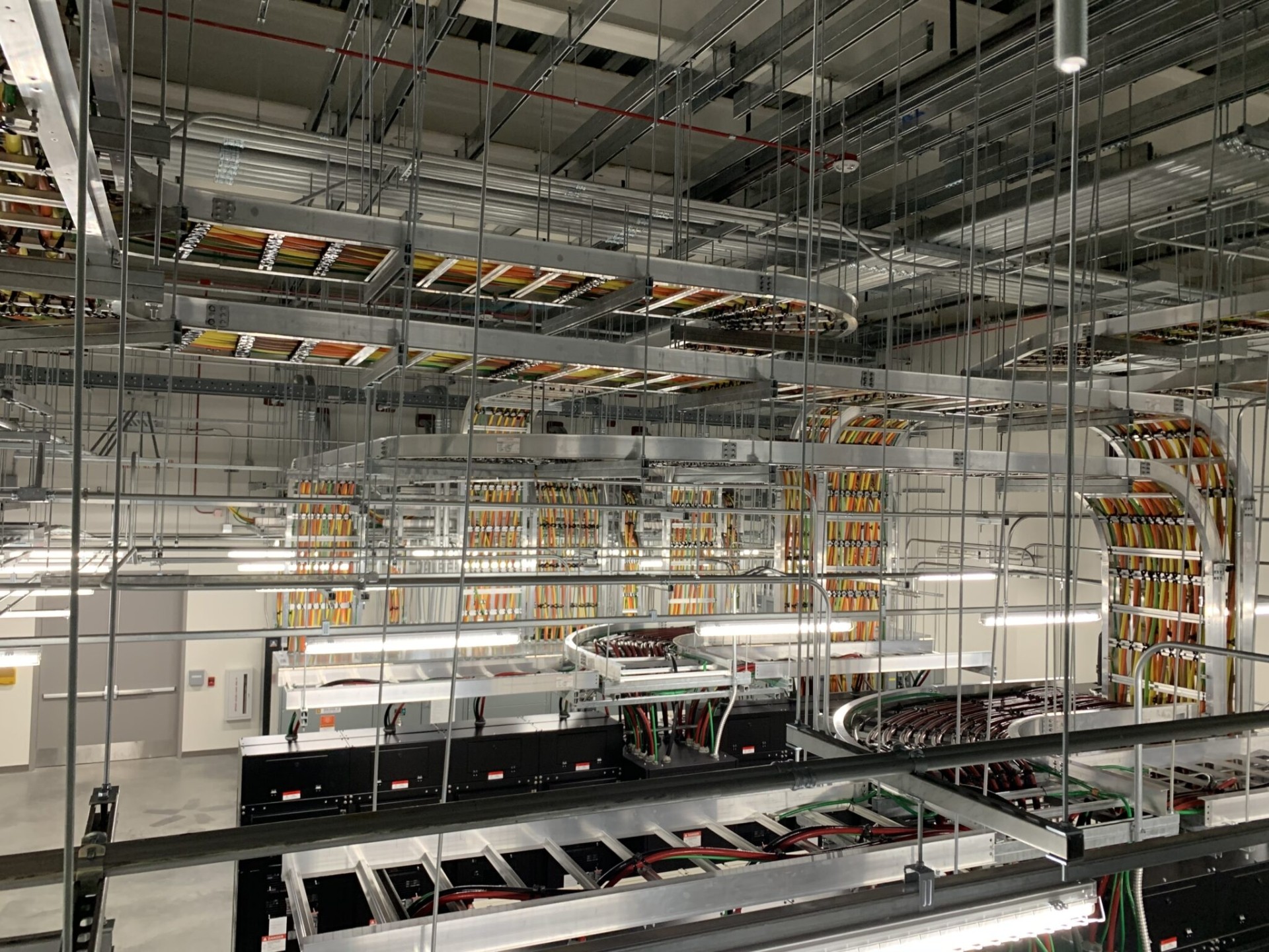
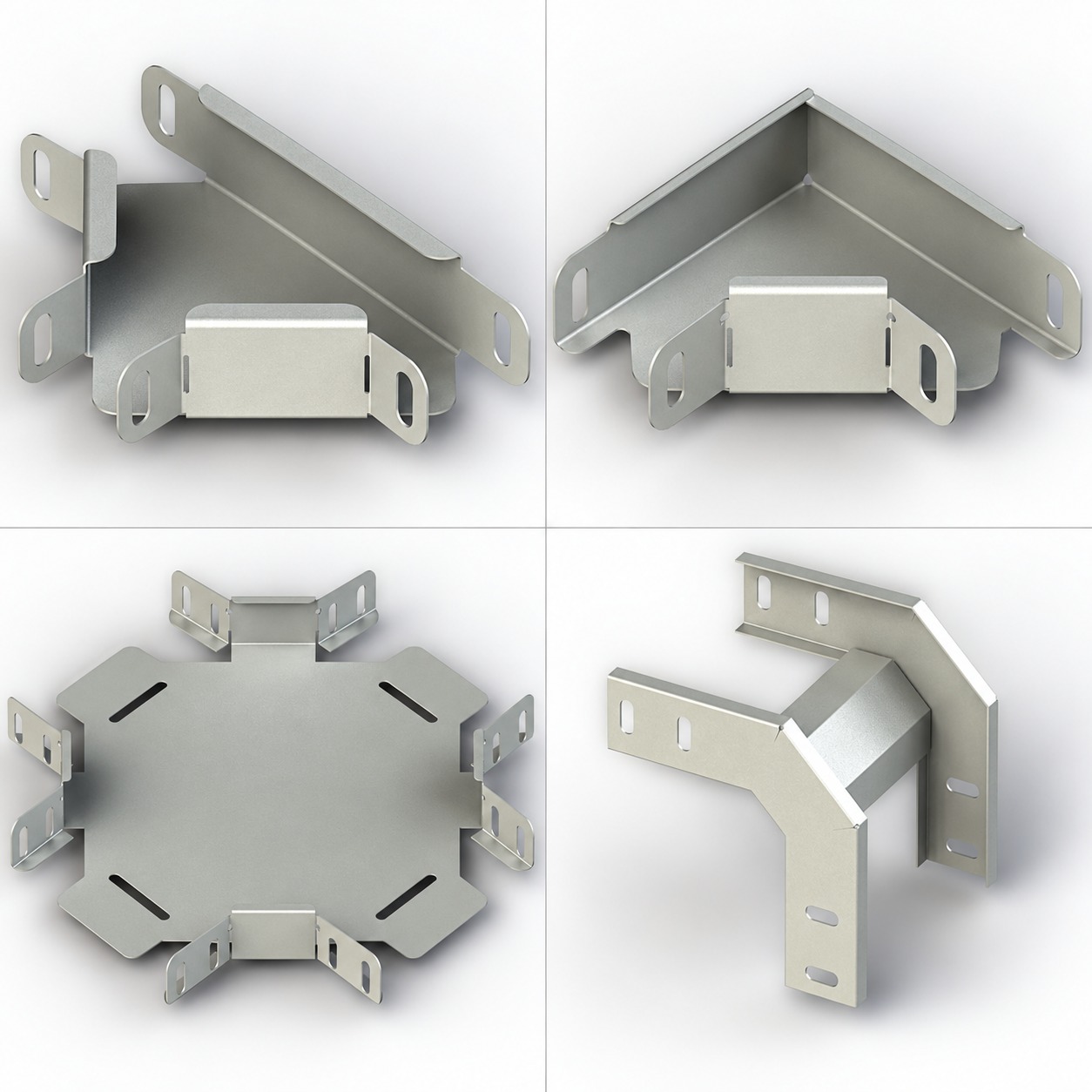
A straight-section result does not validate the complete route. At bends, select a fitting radius at least equal to the largest applicable cable minimum bend radius. ABB states that fitting radius is normally governed by cable rigidity and the cable manufacturer’s minimum bend allowance.[8]
At tees and crosses, recalculate each outgoing segment after cables split. Check inside-radius crowding and avoid cable crossover. Size reducers for the downstream requirement.
For vertical runs, verify cable restraint, fastener spacing, fitting support, and permitted vertical loading. CTI notes that ladder rungs, ventilated perforations, and wire-mesh grids can provide anchoring points.[4] Restraints must withstand project-specific fault forces where relevant.
Branches and fittings affect supports. Panduit’s product-specific guide places supports near vertical transitions and large sweeping bends.[7] Use the selected manufacturer’s instructions.
Tray, ladder, wire mesh, or trunking
Pathway type changes the checks:
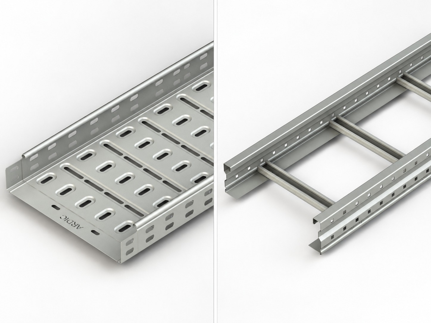
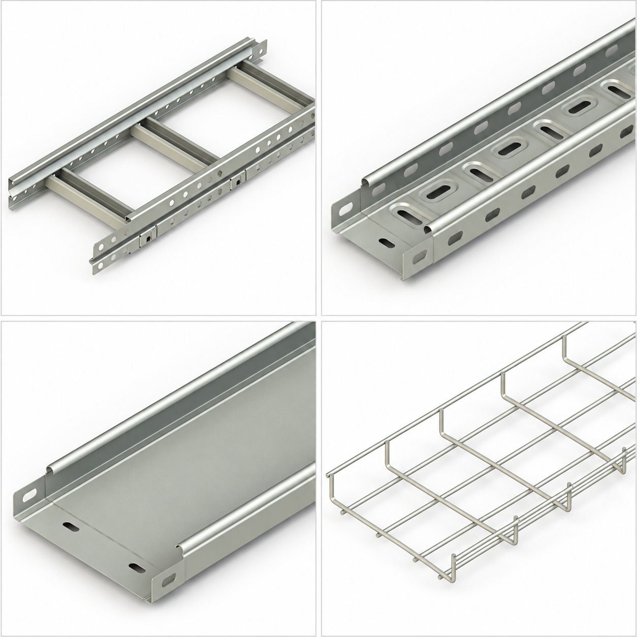
- Perforated or solid-bottom cable tray: continuous support can suit smaller cables. Perforations aid ventilation and drainage; solid bottoms reduce both.
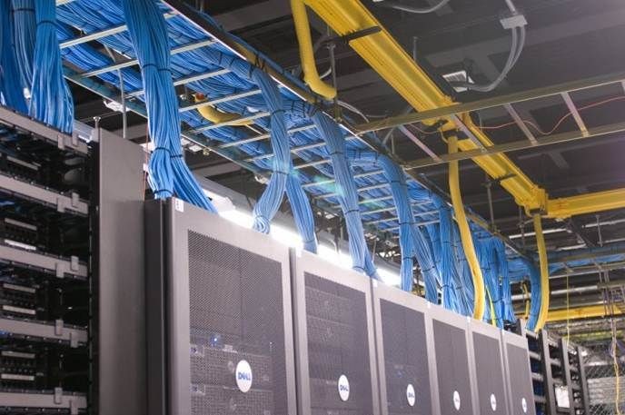
- Cable ladder: open rungs promote airflow and offer restraint points. Rung spacing must support small cables while allowing larger cables to exit within bend limits; relevant product families are grouped under ARDIC’s cable ladder range.
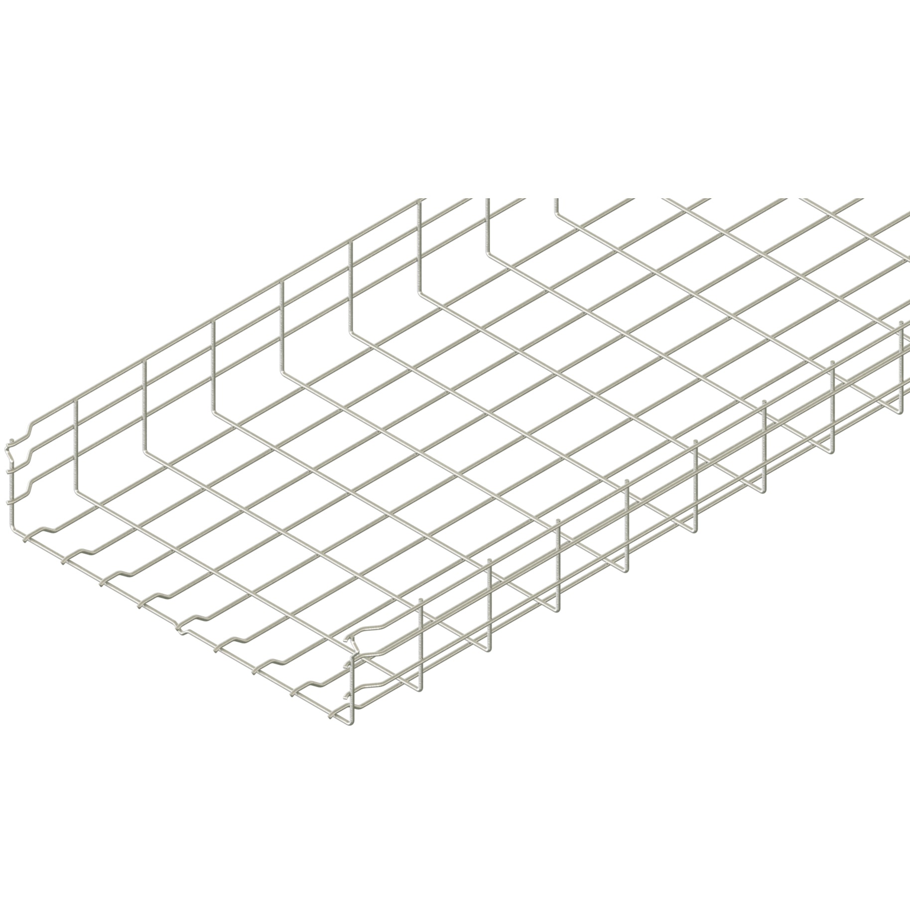
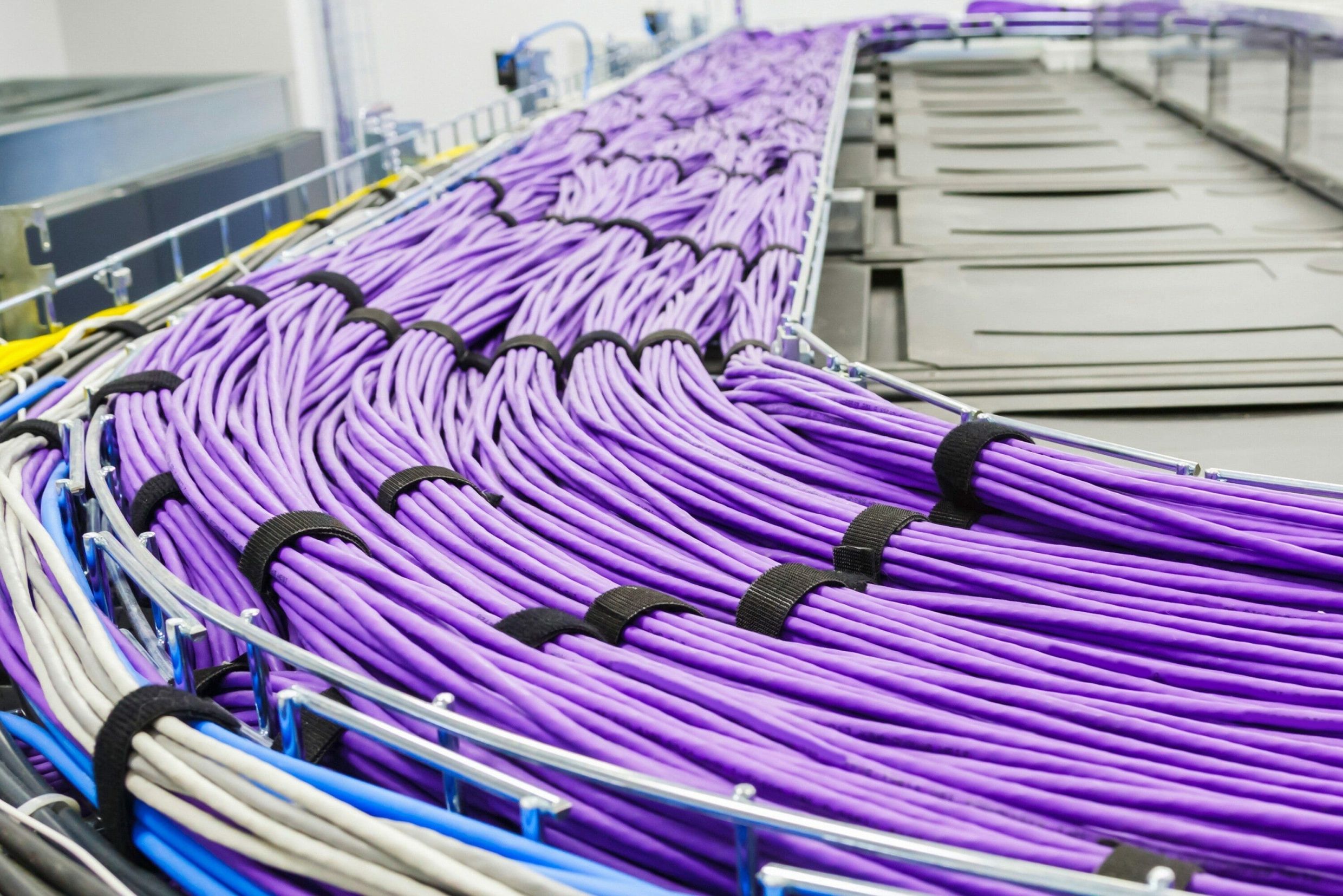
- Wire mesh: field adaptability can suit data, control, and light-power routes, subject to load, span, edge, and support requirements. ARDIC’s wire mesh category lists the corresponding product families.
- Cable trunking: generally forms a more enclosed cable-management system. IEC 61537 expressly excludes trunking from its cable tray and ladder scope, so do not apply tray-system assumptions automatically.[1] ARDIC's trunking category groups products of this format.
CTI’s type-selection bulletin says open ladder trays provide maximum free airflow, while solid-bottom trays have limited drainage and airflow.[4] Type selection therefore belongs before final sizing, not after it.
Grouping, thermal, and code limits
Physical fit is only one gate. Grouped current-carrying cables can retain heat, and covers can change dissipation. Check ampacity, ambient temperature, solar exposure, grouping, spacing, load cycle, and covers under applicable rules.
Segregation consumes width. Voltage classes, EMC-sensitive circuits, fire-alarm circuits, redundant supplies, or owner rules may require separate compartments or pathways. Treat each compartment as its own envelope.
Standards have different jobs. NEMA VE 1 specifies requirements for metal trays and fittings used under NEC and CEC rules.[2] CTI says VE 1 covers construction, testing, and performance, while VE 2 addresses installation and maintenance.[3] IEC 61537:2023 covers system requirements and tests, including revised safe-working-load procedures.[1] Installation rules determine allowable cables, fill, ampacity, grounding, and local restrictions.
Hypothetical worked example
Educational assumptions only: This example does not represent an ARDIC product or a universal design rule. Assume one horizontal indoor segment contains 20 control cables with 14 mm OD and 0.32 kg/m weight, plus six power cables with 32 mm OD and 2.10 kg/m weight. The project engineer has approved a 25% allowance on scheduled cable area and weight, and a 40% preliminary area-fill criterion for this cable mix.
- Control-cable area:
20 × π × 14² / 4 = 3,079 mm². - Power-cable area:
6 × π × 32² / 4 = 4,825 mm². - Installed area:
3,079 + 4,825 = 7,904 mm². - Design cable area with allowance:
7,904 × 1.25 = 9,880 mm². - Preliminary required usable area:
9,880 / 0.40 = 24,701 mm². - A hypothetical 300 × 100 mm usable envelope provides
30,000 mm²; design fill is9,880 / 30,000 × 100 = 32.9%. - Installed cable weight:
(20 × 0.32) + (6 × 2.10) = 19.0 kg/m. - Design cable weight with allowance:
19.0 × 1.25 = 23.75 kg/m.
The result is only a candidate. If the six power cables must remain in one layer, their diameter sum is 6 × 32 = 192 mm before required spacing. Also verify stacking, thermal derating, segregation, fitting radius, tray self-weight, support span, and manufacturer load data.
Decision table
| Check | Input | Pass condition | If it fails |
|---|---|---|---|
| Area fill | OD, quantity, usable area | Within the applicable project/code method | Increase usable size or split the route |
| Width arrangement | OD, spacing, layers | Cables fit in the permitted arrangement | Increase width or use parallel trays |
| Height and access | Cable layers, cover, exits | No crushing; installation and maintenance remain practical | Increase depth or revise layout |
| Thermal | Current, grouping, ambient, cover | Ampacity calculation passes | Add spacing, change type, split circuits, or resize cable |
| Bends | Cable minimum radius | Fitting radius meets every cable requirement | Select a larger radius or reroute |
| Structural | Cable load, tray weight, span, other loads | Manufacturer’s tested load/span data passes | Change tray, span, or support design |
| Segregation | Circuit classes and project rules | Required separation is maintained | Add divider or separate pathway |
| Future capacity | Approved future schedule | Area and final load both pass | Reserve another route or larger system |
Common sizing mistakes
- Applying one favourite fill percentage to every cable type and jurisdiction.
- Using conductor area instead of finished cable OD.
- Calculating area but ignoring a single-layer or spacing rule.
- Treating nominal width and height as fully usable dimensions.
- Adding future area without adding future cable weight.
- Combining cable, tray, and environmental loads into an undocumented number.
- Ignoring branches, bends, drops, and fitting supports.
- Maximizing stacking depth without checking heat, access, or cable damage.
- Ignoring a cover’s effect on ventilation, wind response, and access.
- Transferring manufacturer-specific recommendations to another system.
RFQ input checklist
Provide these inputs:
- route drawing, segment lengths, elevations, branches, and fitting angles;
- cable schedule with quantities, OD, weight, bend radius, service, and future cables;
- proposed usable width and depth, tray type, dividers, liners, and tray covers;
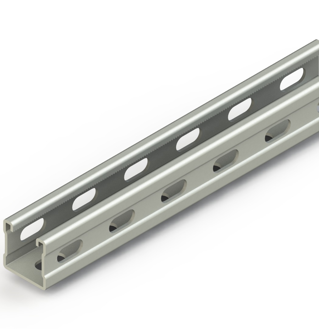
- support span, support arrangement, structural substrate, and concentrated loads;
- location, temperature, corrosion environment, wind, snow, ice, and seismic criteria;
- required material, finish, bonding/grounding approach, and documentation;
- governing code, standard editions, project specification, and approval authority; and
- fittings, couplers, fasteners, drop-outs, restraints, covers, and compatible supporting systems.
The ARDIC cable tray overview groups relevant families; dimensions and performance still require confirmation from current documentation.
Frequently asked questions
Short answers to common cable tray sizing questions.
There is no single percentage that is correct for every tray, cable, and jurisdiction. Determine the applicable rule from the cable type, tray type, code edition, project specification, and manufacturer guidance.
It depends on the governing arrangement. Some checks use total cross-sectional area, while others use diameter sums, spacing, or a required single layer; run every applicable check.
Yes, planned future cables affect both occupied space and distributed cable weight. Size the final tray and supports for the documented future condition, including other applicable loads.
Choose width from cable arrangement, spacing, segregation, and bend access. Choose height from permitted layering and usable depth, then verify thermal performance and maintenance access rather than maximizing fill.
No. Geometry may provide an early comparison, but product scope, cable support, ventilation, load/span performance, fittings, and applicable standards differ. Complete the checks for the selected system.
Conclusion
A sound cable tray sizing calculation begins with a segment-by-segment cable schedule. Calculate geometric occupancy, then verify width arrangement, height, bends, thermal limits, segregation, and future growth. Keep cable load, tray self-weight, support span, and environmental loads visible as separate structural inputs.
For a project-specific review, send ARDIC your cable schedule, route drawing, environment, and project requirements so the relevant tray family and required documentation can be identified.
Sources
- [1] IEC 61537:2023
- [2] NEMA VE 1-2017 Metal Cable Tray Systems
- [3] Cable Tray Institute Codes and Standards
- [4] CTI Technical Bulletin 4: Cable Tray Type Selection
- [5] Eaton Cable Tray Design Considerations Guide
- [6] Eaton Quotation Check List for Cable Tray
- [7] Panduit Wire Basket Overhead Cable Tray Application Guide
- [8] ABB Cable Tray Technical Guide