

Power, Data and Control Cable Segregation in Cable Trays
Power, data and control cable segregation is a route-design and documentation task, not a single tray-detail decision. A cable tray can carry different services only when the project team has identified the circuits, the cable constructions, the equipment interfaces and the applicable rules. The wrong question is “what fixed gap should we use?” The useful question is “what combination of routes, barriers, crossings, bonding interfaces and records does this installation require?”
This guide helps you:
- distinguish EMC coordination from electrical safety, fire stopping and mechanical support;
- turn drawings and cable schedules into a reviewable segregation plan; and
- commission the completed route against the approved design rather than against assumptions.
IEC TR 61000-5-1 describes EMC installation and mitigation as a matter of selecting techniques appropriate to the particular installation; it also separates EMC concerns from safety requirements.[1]
Contents
- [Why segregation starts with a route brief](#route-brief)
- [Classify cables before choosing a tray arrangement](#classify-cables)
- [Choose a documented segregation strategy](#segregation-strategy)
- [Coordinate EMC without treating it as safety compliance](#emc-coordination)
- [Review crossings, transitions and interfaces](#route-interfaces)
- [Keep bonding, fire stopping and support reviews separate](#separate-reviews)
- [Build records for installation and commissioning](#commissioning-records)
- [Common mistakes in cable tray segregation](#common-mistakes)
- [Frequently asked questions](#faq)
- [Sources](#sources)
Why segregation starts with a route brief
Start by defining the route’s purpose and limits. Record the origin and destination, areas passed through, tray family, elevation changes, penetrations, shared sections and interfaces with cabinets, panels or machinery. This route brief makes a later decision traceable: a divider shown on one drawing may be meaningful in one run and unsuitable at a transition or termination.
The brief should identify which discipline owns each decision. Electrical design may own circuit classification and safety separation. Controls and automation teams may own signal integrity requirements. ICT teams may own communications pathway constraints. Fire-stopping design and building coordination may own penetration details. The tray installer needs an approved, coordinated instruction rather than a verbal rule carried from another project.
IEC 61537 covers cable tray and cable ladder systems intended to support and accommodate cables in electrical and communication installations, and notes that systems can arrange cables into groups.[2] That scope is useful context, but it does not replace the project’s cable, equipment, installation or national-standard requirements.
For early coordination, link the route discussion to the site’s cable tray systems and supporting systems references. These pages can help a team name system categories during planning; they are not evidence that any finished route meets an EMC, fire, safety or certification requirement.
Classify cables before choosing a tray arrangement
A schedule should classify each cable by its actual function and characteristics, not only by a short label such as “LV” or “data.” Typical fields include circuit function, source and destination, nominal system information, cable type, shielding or screen details, termination method, route segment, environment and any stated manufacturer or equipment constraints. Where a system mixes power, analogue instrumentation, digital control, communications and fibre, the schedule should preserve those distinctions.
The classification should also flag interfaces that change the evaluation. A screened control cable may have a termination requirement. A communications cable may have pathway rules supplied by its owner. A circuit entering an enclosure can change from a tray-routing issue to a cabinet-entry issue. A fibre route may have handling and bend-management constraints that do not answer questions about nearby power circuits.
Do not infer an EMC outcome from a cable name. Coupled-noise concerns must be evaluated in the context of the actual installation, the equipment involved and the selected mitigation approach. IEC’s installation guidance places responsibility on the designer and installer to select techniques appropriate to the particular installation.[1] That is a useful model: identify the disturbance concern, the susceptible system and the project-approved response.
A practical cable schedule also separates confirmed information from open items. Mark unknown shield terminations, missing equipment instructions, undecided crossing locations and incomplete penetration details. Closing these items before installation is safer than converting them into field improvisation.
Choose a documented segregation strategy
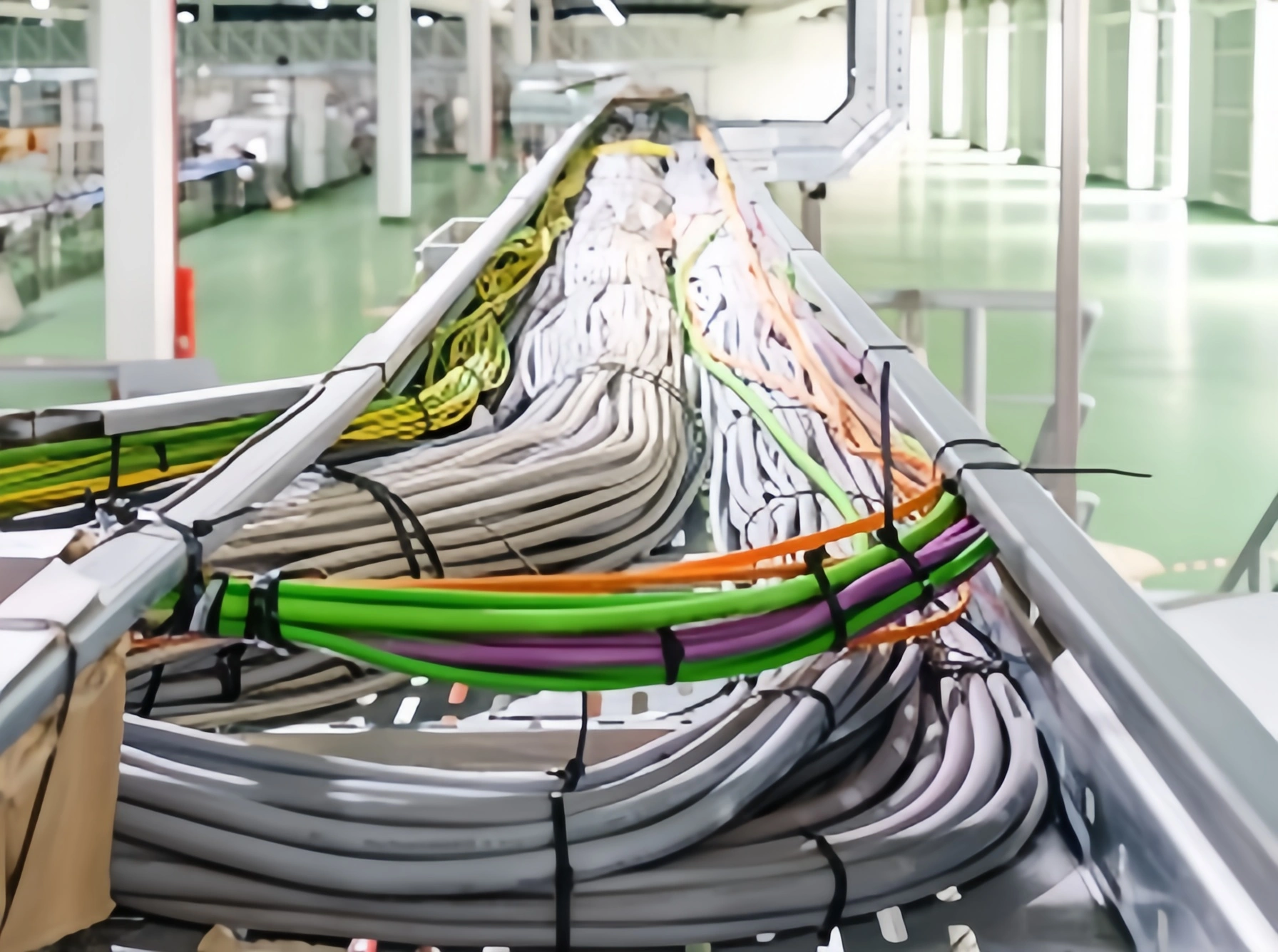
Segregation can use separate tray routes, dedicated compartments, a metallic divider, controlled crossing geometry, different elevations or a combination of these. None is automatic compliance. The appropriate option depends on the cable constructions, circuit conditions, route length, environment, equipment documentation, applicable national rules and the project specification.
Separate trays can make identification and future maintenance clearer, but they create coordination work at risers, branch points and equipment entries. A divider can retain a common support route, but its material, continuity, height, fixing method and treatment at fittings must be assessed for the actual system. A shared tray with planned group locations can be workable only when the design documents define those groups and their transitions.
Use a route matrix to compare options. For every shared segment, state the cable groups present, the chosen measure, the drawing reference, responsible reviewer and unresolved conditions. Include the reason for the choice, but avoid wording such as “divider equals EMC compliance.” The record should say what was reviewed and what still needs verification.
Where a project uses a cable ladder route, the same discipline applies. Review the cable ladder system as a route component, then assess its fittings, supports and interfaces against the approved documentation. A product-category page is not a substitute for a system-specific engineering review.
Coordinate EMC without treating it as safety compliance
EMC coordination asks whether emissions, coupling paths and susceptible equipment have been considered together. It is not the same as protecting people from electrical hazards, proving continuity of a protective conductor or meeting a fire-resistance requirement. IEC TR 61000-5-1 explicitly says its EMC practices address installation EMC concerns rather than safety or efficient power transport, while recognizing that relevant safety requirements must also be applied.[1]
For each route, record the EMC assumptions: likely sources of disturbance, susceptible circuits, cable-screen information, termination expectations, shared-route lengths, crossings, metalwork interfaces and equipment-maker instructions. This makes the review specific enough for the engineer or specialist who must decide the mitigation approach.
Treat metallic components carefully. A divider or tray body may alter the physical arrangement, but it does not by itself prove screening effectiveness, bonding performance or an equipment-level EMC result. A screen can also depend on its cable construction and termination. Likewise, a choice that improves physical separation may not satisfy electrical-code requirements. Keep the design intent explicit and obtain qualified review where the project requires it.
Avoid retrospective guarantees such as “this layout eliminates interference.” Commissioning can confirm that installed routes match drawings and that documented checks occurred. It cannot turn an undocumented assumption into a universal performance claim.
Review crossings, transitions and interfaces
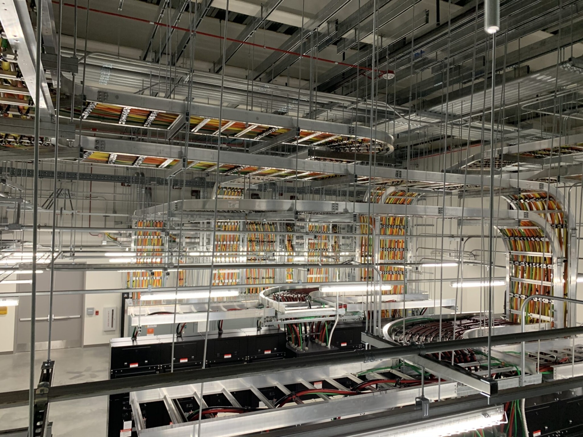
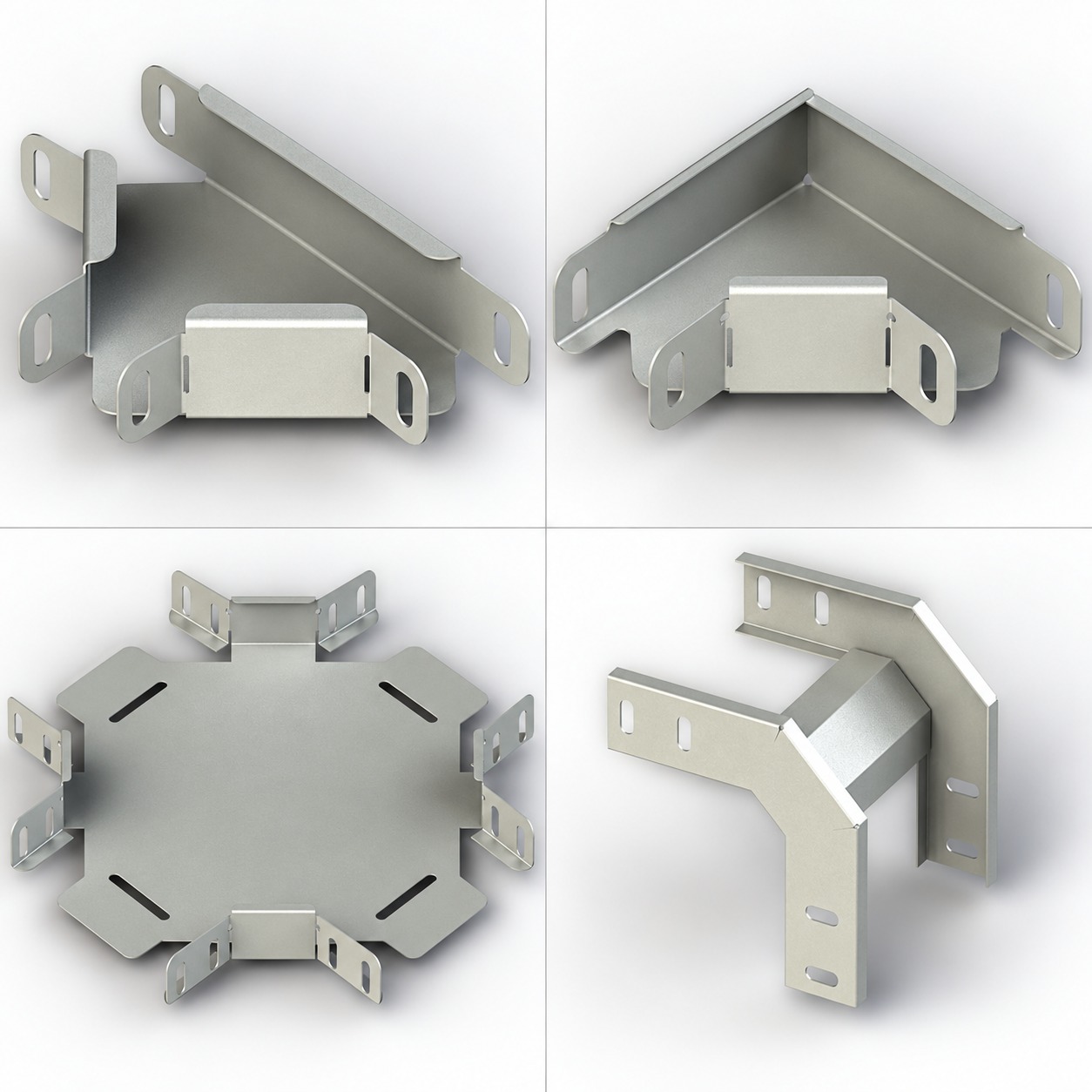
Straight tray sections are only part of the route. Crossings, tees, reductions, risers, cover changes, drop-outs and cabinet entries are where a neat segregation concept often loses continuity. Put these locations on coordinated drawings and require an installation review before cable pulling where they are critical.
At a crossing, define the cable groups, the intended geometry, the local containment arrangement and the authority for any change. At a branch, show which group remains in which compartment or route. At a cabinet or panel, check entry positions, gland or termination instructions, screen-handling details and the boundary between tray work and equipment work. Do not let a generic fitting detail decide an electrical or EMC interface.
This is also the point to revisit installation documentation. UL describes cable trays as mechanical support systems and notes that metallic trays can be evaluated in relation to an electrical ground path in applicable contexts.[3] That statement does not establish the suitability of an individual tray route, component mix or bonding arrangement. Use the project’s applicable rules, equipment instructions and qualified review for those determinations.
Keep bonding, fire stopping and support reviews separate
Bonding and earthing interfaces deserve their own record. Identify tray sections, joints, dividers, supports, transitions and connections that the approved design requires to be addressed. Record the drawing, specification or equipment document that governs each interface. Do not describe a mechanical joint as proof of electrical continuity, and do not assume a continuity measure resolves an EMC issue.
Fire stopping is another independent review. At every wall or floor penetration, capture the opening location, services passing through, the approved penetration system, installation instructions, inspection evidence and any changes in cable population. A route’s segregation arrangement does not demonstrate the suitability of the fire-stop system, and a penetration detail does not prove the route’s EMC coordination.
Mechanical support is equally distinct. Cable groups, partitions, covers, fittings and future additions can affect the completed installation, but this article gives no support spacing, fill, load or cable-count prescription. Confirm those matters against current product documentation, project drawings, applicable standards and qualified engineering review. The IEC 61537 cable tray tests and documentation guide can provide context on system documentation, not configuration approval.
Build records for installation and commissioning
A release-ready package includes more than a layout drawing. Assemble a controlled set of documents: route plans, sections, cable schedule, segregation matrix, equipment instructions, change log, penetration register, bonding-interface register, inspection forms and photographs. Give every route segment an identifier that appears consistently across drawings and site records.
Before cable pulling, compare the work area with the latest approved drawings. Confirm tray identity, intended cable groups, divider or route boundaries, planned crossings, fittings, supports and interfaces. Record deviations immediately. If a field condition forces a change, stop treating the original drawing as proof; route the change through the project’s review process.
During commissioning, use a checklist that asks whether the installed grouping matches the controlled route plan, whether labels can be read, whether transitions were inspected, whether required bonding and fire-stop records are complete and whether open items have owners. Include the date, reviewer, evidence reference and disposition for each item. This produces a usable handover record without claiming an untested performance result.
For project-specific help interpreting documentation and route interfaces, use the single commercial contact point: contact Ardıç Elektrik. A clear, controlled record remains the basis for future modifications.
Common mistakes in cable tray segregation
The most common failure is importing a fixed separation value from another project without checking cable types, equipment, local adoption and installation conditions. Another is calling every low-voltage cable “data,” which hides differences between communications, instrumentation and control circuits. Both shortcuts make later verification difficult.
Other avoidable mistakes include:
- showing a divider in plan view but omitting its treatment at fittings and entries;
- treating a metallic tray, divider or cover as automatic EMC or protective-earthing proof;
- mixing fire-stop, bonding, support and segregation approvals into one unchecked sign-off;
- allowing installers to resolve unknown transitions without an approved detail; and
- handing over photographs without route IDs, drawing revisions or cable-group labels.
A better close-out process traces each physical arrangement back to the latest controlled document. If evidence is missing, record the gap and assign it for review instead of filling it with a generic claim.
Frequently asked questions
Short answers for route planning and documentation.
No. A universal distance would ignore cable construction, circuit conditions, equipment documentation, route configuration, applicable standards and national adoption. Use the project documents and qualified engineering review to select and record an approach.
No. A divider is a possible physical-arrangement measure. Its relevance depends on the complete installation, including cable types, continuity, interfaces, termination details and the project’s EMC assessment.
A shared route must be assessed against the applicable electrical, functional and EMC requirements. If it is allowed by the project design, the approved drawings should identify groups, boundaries, crossings and transition details rather than relying on an informal field convention.
Bonding and earthing are separate design subjects from EMC performance, even though they can interact in an installation. Confirm the required bonding arrangement and the EMC approach through the governing documents and qualified review.
Compare the installed route with the approved segregation plan, then close records for labels, transitions, deviations, required bonding interfaces and fire-stop inspections. Retain route IDs, drawing revisions, photographs and unresolved-item ownership in the handover file.