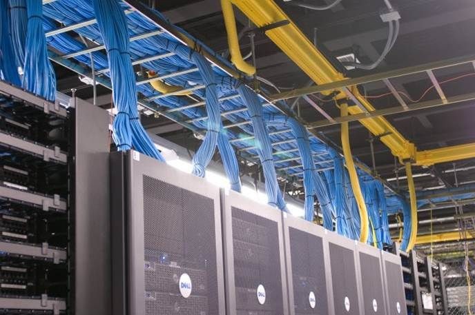


Cable Tray Installation Guide and Inspection Checklist
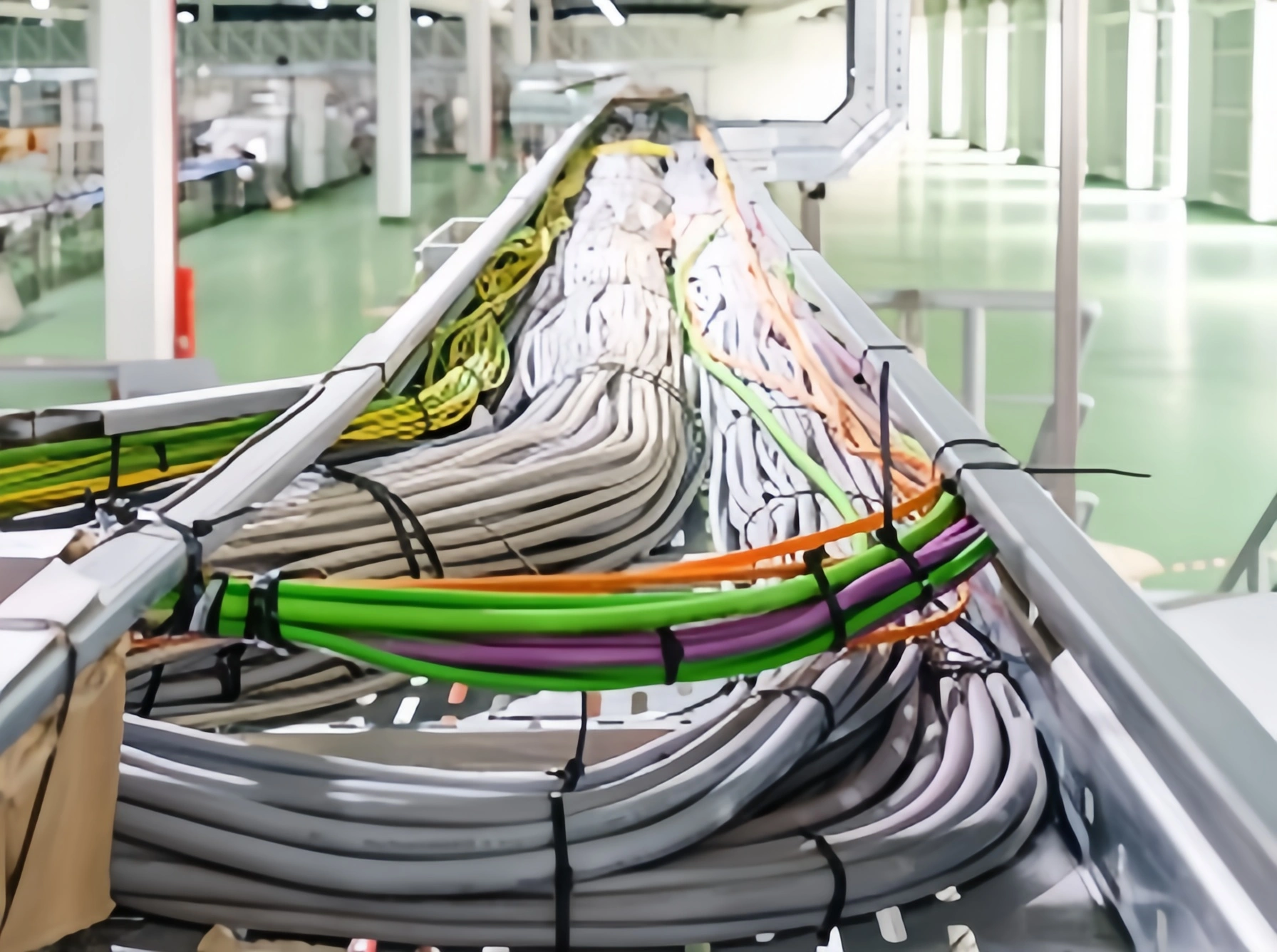
A straight-looking run can still hide weak supports, misplaced joints, damaged finishes, or an incomplete bonding path. A reliable cable tray installation therefore begins before the first bracket goes up and ends only after inspection records match the installed route.
This guide gives qualified designers, supervisors, installers, and inspectors a practical sequence for receiving materials, setting out the route, assembling the system, installing cables, and closing the work. It is not a substitute for approved drawings, permits, local law, project specifications, cable instructions, manufacturer documents, or competent supervision.
Table of contents
- Establish the installation basis
- Receive, handle, and store the system
- Set out the route before drilling
- Install and inspect the support system
- Assemble straight sections, joints, and fittings
- Coordinate expansion, penetrations, and interfaces
- Verify bonding and protective earthing
- Prepare for cable installation
- Use the practical inspection checklist
- Avoid common installation mistakes
- Frequently asked questions
- Conclusion
- Sources
Establish the installation basis
Start by identifying which documents control the work. Keep the manufacturer’s instructions, project documents, applicable law or code, and site safety procedure distinct. They may address different risks, and the strictest applicable requirement may govern.
The Cable Tray Institute describes VE 2 as practical guidance for engineers, contractors, and maintenance personnel. It identifies VE 2 separately from manufacturing standards and installation codes.[1] Use that distinction to organize the work, but check jurisdiction and product applicability for each project.
Before mobilization, confirm:
- approved route drawings, sections, details, and revision status;
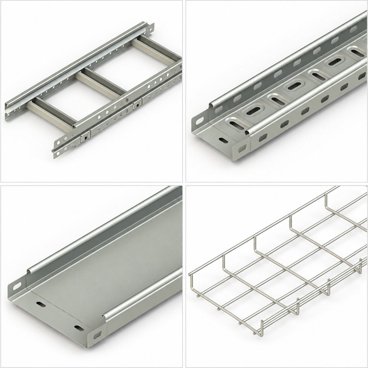
- tray or ladder family, material, finish, width, side height, fittings, and accessories;
- cable schedule, segregation plan, design load, fill basis, and future capacity policy;
- support types, anchor design, joint rules, and special-support details;
- bonding and protective-earthing design;
- firestopping, waterproofing, access, and inspection hold points; and
- permits, isolation boundaries, lifting plan, and work-at-height controls.
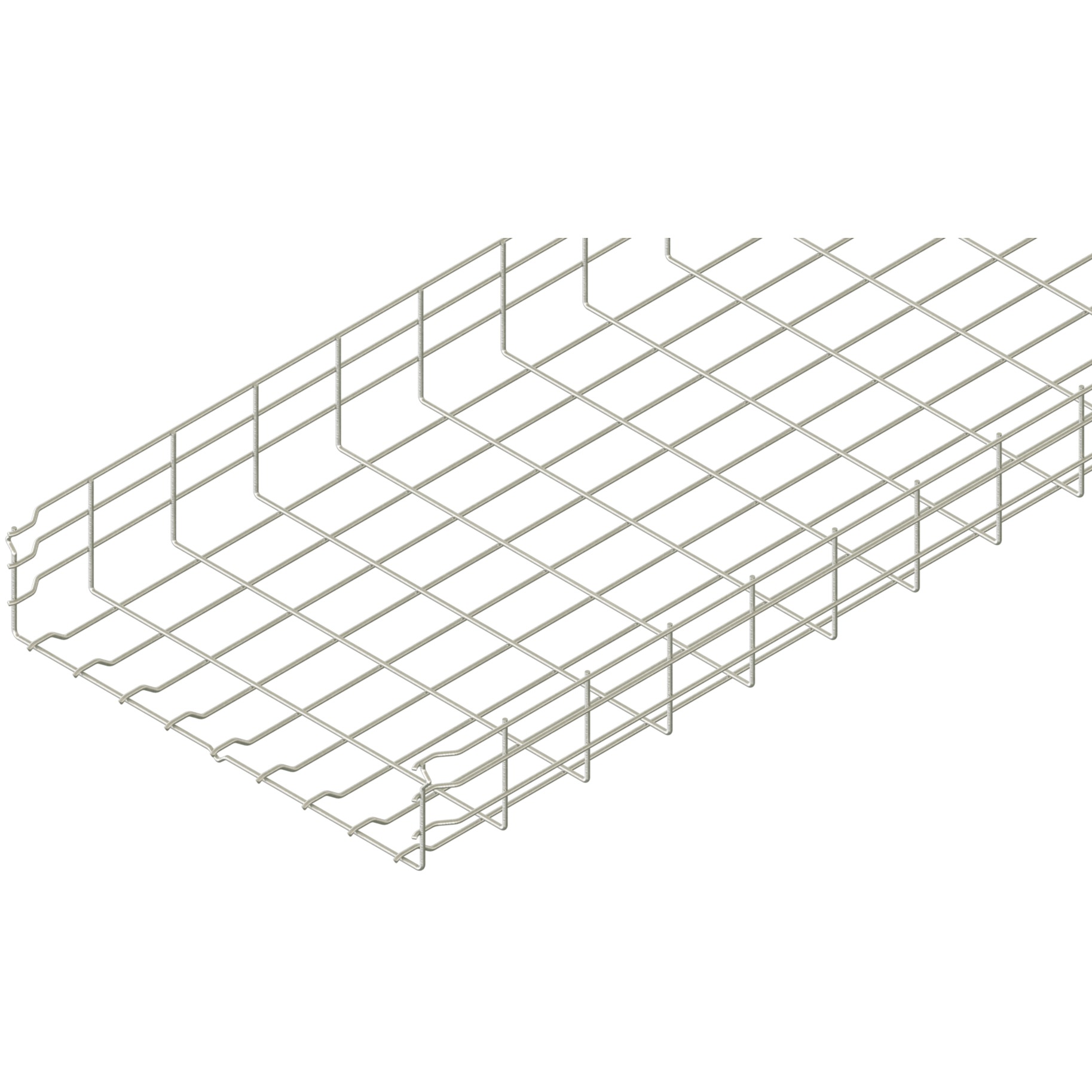
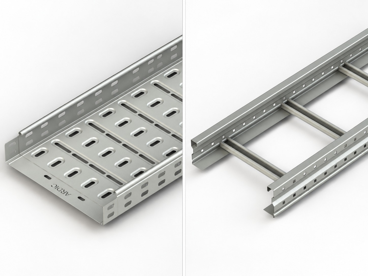
Review cable tray systems and cable ladder systems only as product categories during coordination. Final selection and installation details require current documents for the exact system.
Receive, handle, and store the system
Inspect deliveries against the approved submittal before distribution. Separate similar-looking parts with different materials, finishes, thicknesses, or hardware.
Record shortages, damage, wet packaging, and unidentified components. Quarantine anything that cannot be matched to the approved system.
Use handling methods that avoid twisting sections or crushing rails and rungs. Store components on stable dunnage as the manufacturer requires. Keep fasteners and connector kits dry, labelled, and traceable.
Before installation, check edges, welds, perforations, and contact surfaces without making unapproved repairs. Approved touch-up treatment may differ by material and finish.
Set out the route before drilling
Transfer the latest coordinated route to the work area. Mark elevations, centerlines, direction changes, branch points, risers, equipment entries, expansion locations, and penetrations. Verify the marks against actual structure and other services rather than relying only on a drawing scale.
Walk the route with relevant trades. Check work and maintenance access, equipment, other services, crane paths, and reserved areas. Resolve clashes before drilling or cutting.
Treat straight runs, fittings, vertical runs, changes of direction, expansion points, and penetrations as different coordination cases. A straight-section spacing rule cannot automatically define support around a bend, tee, reducer, drop, or riser.
Confirm that penetrations suit the designed assembly without damaging cables or tray edges. The responsible discipline must define firestopping, weather sealing, opening details, and edge protection.
Install and inspect the support system
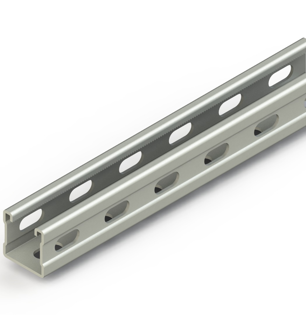
The support assembly transfers tray, cable, accessory, and project loads into the structure. Brackets, channels, rods, anchors, fasteners, and base material all belong to that path. Review supporting systems as a component category, then verify the exact assembly against approved documents.
Install supports at the project-defined locations and orientations. Support spacing is system- and project-specific; do not replace the approved schedule with a familiar site rule. Obtain design review where obstructions force relocation.
During inspection, check that:
- the anchor type, embedment basis, edge conditions, and substrate match the approved detail;
- brackets and trapezes are level, aligned, correctly oriented, and securely assembled;
- threaded components have the specified engagement and locking arrangement;
- support projections do not create an unreviewed lever arm;
- finishes remain intact or receive an approved repair; and
- supports do not rely on unrelated services unless the design expressly permits that interface.
Do not stand, sit, or walk on cable tray. It is a cable-support system, not personnel access equipment. Use approved work platforms and lifting equipment under the site plan.
Assemble straight sections, joints, and fittings
Build from a controlled reference point without forcing alignment. Use specified connectors, fasteners, washers, hold-downs, and splice hardware. Mixed hardware can alter performance, corrosion behaviour, or electrical continuity.
Place joints only where the approved layout and manufacturer instructions permit. Follow the specified fastener-tightening method and product-specific torque where one is given; there is no universal torque for all tray systems. Mark completed critical connections only when the project quality plan requires it.
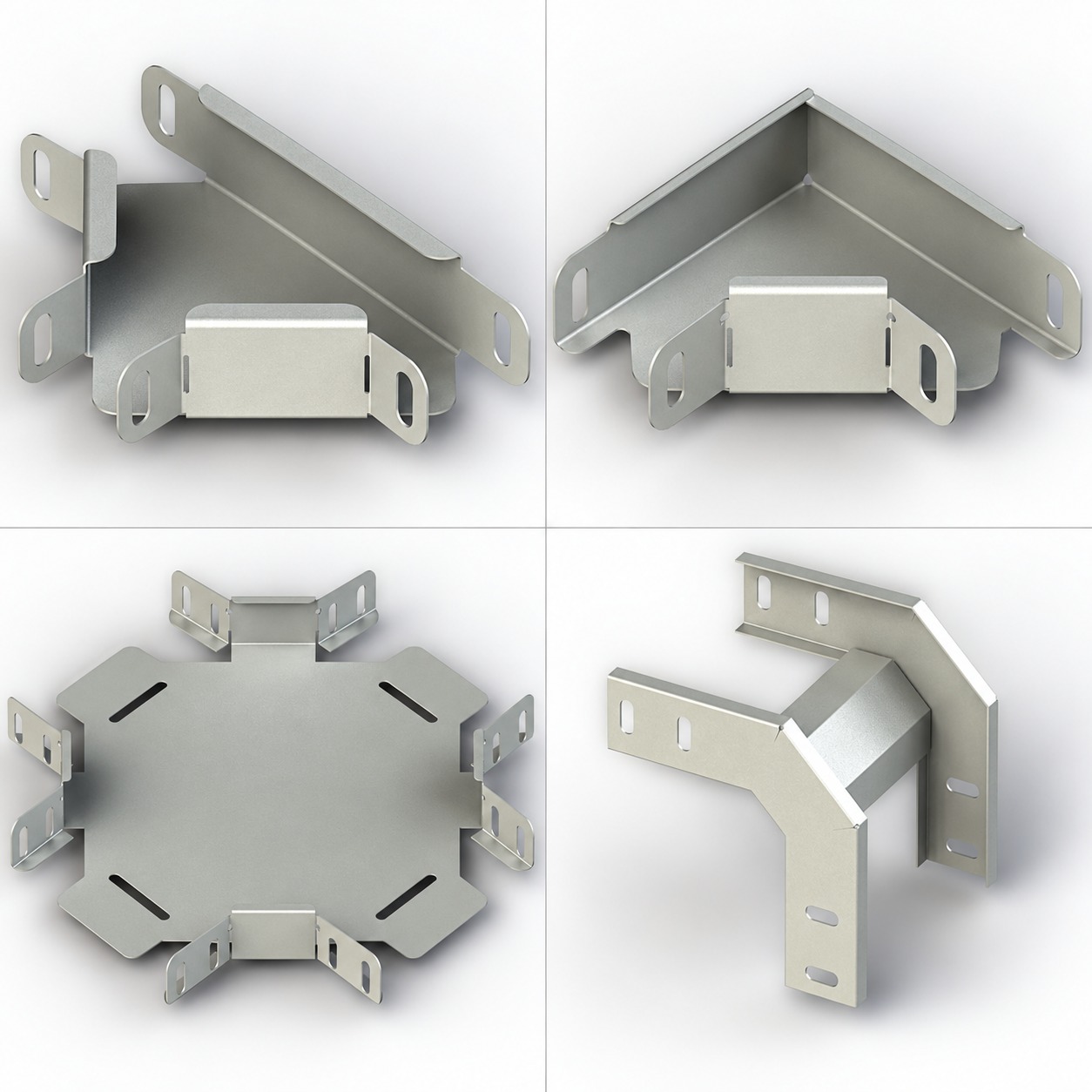
Support bends, tees, crosses, reducers, vertical transitions, and cable drop-outs according to their approved details. Fittings redistribute load and may need support arrangements that differ from straight sections. Never assume a nearby straight-run support is sufficient.
For field cuts, use an approved method that avoids distortion and hazardous burrs. Remove sharp edges, restore corrosion protection with the specified system, and use purpose-made fittings where required. Field fabrication must not be assumed to retain a tested straight-section rating.
Keep accessories identifiable and correctly oriented. Preserve access for inspection and cable work.
Coordinate expansion, penetrations, and interfaces
Temperature changes move tray materials. Building joints, outdoor exposure, long routes, and equipment interfaces can introduce relative movement. The Cable Tray Institute’s technical bulletin explains that thermal compensation requires deliberate expansion features and that a structure’s movement solution does not automatically solve tray movement.[2]
Do not copy the bulletin’s example dimensions or historical code references into a different system. Determine expansion locations, gaps, anchors, guides, nearby supports, and bonding jumpers from current manufacturer information and the project design. Record ambient or tray temperature when the approved setting method requires it.
At penetrations, verify opening approval, edge protection, clearances, movement, and sealing before cables obscure the area. Do not use tray to impose alignment forces on equipment; coordinate flexible connections or independent support where required.
Verify bonding and protective earthing
Bonding and protective earthing are related but not interchangeable. Bonding establishes the intended electrical continuity between conductive parts. Protective earthing connects relevant exposed conductive parts to the installation’s earthing arrangement. Mechanical connection alone does not prove that either function meets every requirement.
Follow the approved electrical design through straight sections, fittings, material transitions, expansion joints, flexible points, covers where applicable, and equipment interfaces. Coatings, contamination, corrosion, missing hardware, or an unapproved substitute can interrupt the intended path.
Inspect bonding jumpers, lugs, conductors, attachment points, protection from damage, and identification. Required test method, instrument, acceptance criteria, and records must come from the project and applicable requirements; do not invent a universal resistance value. The cable tray grounding guide gives broader conceptual context, not a site-specific electrical design.
Prepare for cable installation
Complete and inspect the tray route before loading cables. Confirm that supports, joints, fittings, covers scheduled for early installation, bonding work, edge treatment, and penetration preparations are accepted. Remove swarf, packaging, standing water, and debris.
Use the cable manufacturer’s limits for bend radius, pulling tension, sidewall pressure, temperature, and handling. Use the project’s cable schedule and segregation design for placement. None of these values is universal, and tray fitting radius does not by itself prove that a cable’s bending requirement is satisfied.
Plan work so cables do not drag across edges, crush circuits, overload an area, or transfer unreviewed force into fittings and supports. Use approved pulling equipment, communication, and stop criteria. Keep workers clear of stored energy and pinch zones.
Apply the site’s isolation and permit procedure. Qualified personnel must determine the applicable procedure, confirm the work boundary, and decide whether the work is de-energized; this guide does not authorize live work.
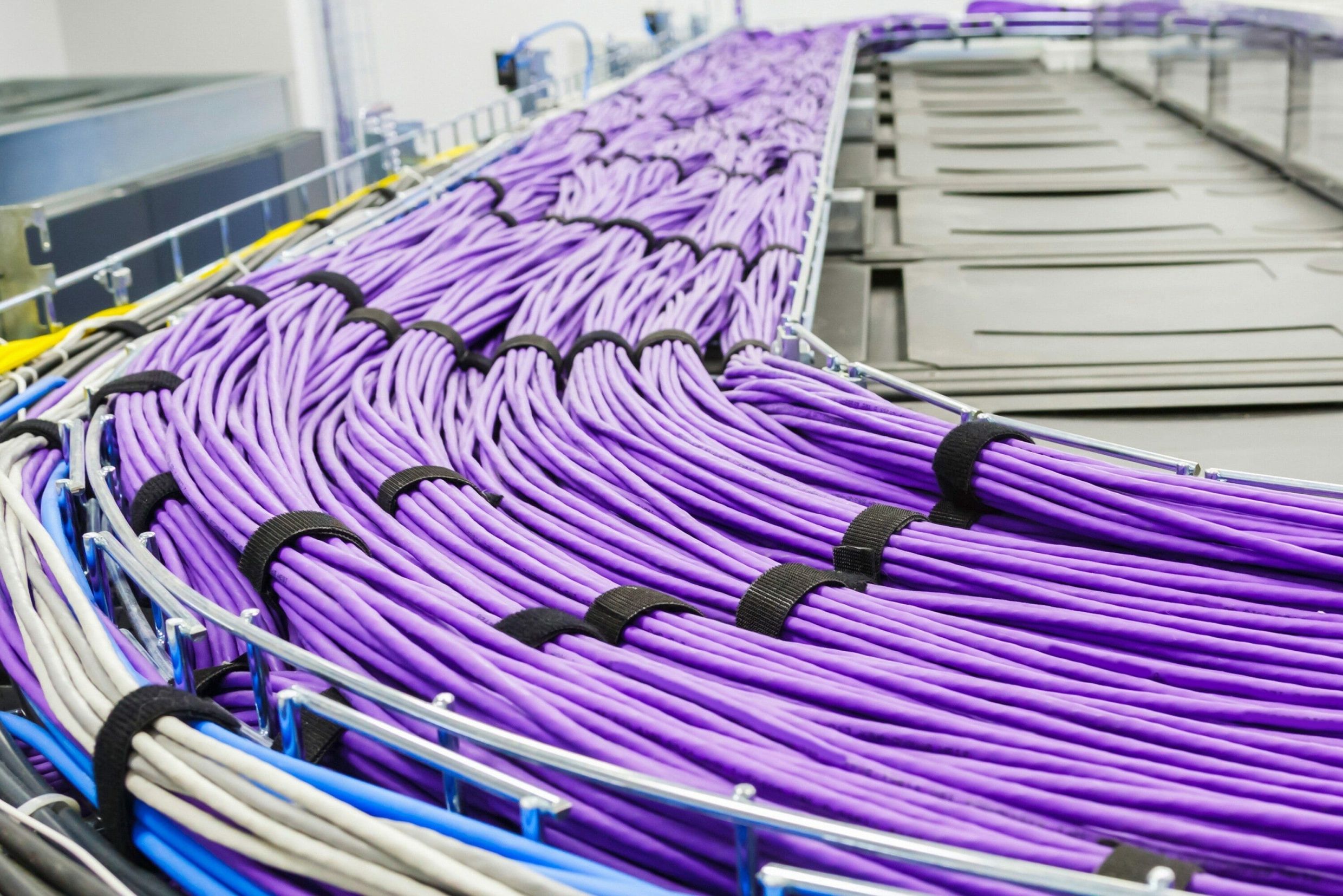
After installation, verify arrangement, securing, separation, identification, entry protection, and capacity against approved documents. Spare space does not authorize additions.
Use the practical inspection checklist
Use this checklist with the project inspection and test plan. Mark each item accepted, rejected, not applicable, or pending, and attach evidence where required.
Pre-installation
- Latest approved drawings, submittals, method statement, and permits are available.
- Materials match the specified system and remain traceable.
- Damage, storage condition, and coating condition are accepted.
- Route, levels, clashes, access, penetrations, and hold points are coordinated.
- Support, expansion, bonding, earthing, and cable-installation details are approved.
Supports and tray assembly
- Supports and anchors match approved types, locations, and substrate conditions.
- Straight runs are aligned without forcing or visible distortion.
- Joints, fasteners, hold-downs, and splice positions follow system instructions.
- Bends, branches, reducers, risers, and transitions have their required supports.
- Cut edges are smooth and receive the specified corrosion treatment.
- Expansion components, guides, anchors, and gaps match the approved setting.
- Penetrations have approved edge protection and sealing coordination.
Electrical and cable work
- Bonding and protective-earthing arrangements match the electrical design.
- Jumpers and connection points are accessible, protected, and identified.
- Required continuity or earthing tests have approved criteria and calibrated instruments.
- The route is clean and accepted before cables are installed.
- Cable limits, segregation, fill, loading, securing, and identification match approved documents.
- Covers and accessories are fitted in the specified locations without trapping or damaging cables.
Handover and maintenance
- Deviations and nonconformities are resolved or formally accepted.
- As-built route, support changes, expansion points, and bonding details are recorded.
- Inspection reports, test results, material records, and photographs are complete.
- Access remains available for inspection, cleaning, repair, and future cable changes.
- Maintenance frequency reflects environment, vibration, corrosion, loading, and site experience.
Avoid common installation mistakes
Starting from an uncoordinated drawing. Small route conflicts become field cuts, unsupported fittings, and blocked access.
Applying one spacing everywhere. Supports near fittings, vertical runs, joints, expansion points, and penetrations require configuration-specific review.
Forcing misaligned sections together. This can preload joints, distort the route, and hide a set-out error.
Treating every metal joint as an electrical bond. Mechanical contact does not automatically satisfy the approved bonding and earthing design.
Using generic torque, bend-radius, or test values. These belong to the exact product, cable, instrument procedure, and project.
Loading before inspection. Cables can conceal fasteners, cut edges, jumpers, and penetration defects.
Closing records late. If marked-up drawings and inspection evidence lag behind the work, later verification becomes unreliable.
Frequently asked questions
Concise answers to common cable tray installation questions.
Confirm approved drawings, exact system components, cable data, support and anchor design, route coordination, bonding and earthing details, permits, and site safety controls. Also inspect delivered materials and resolve damage or identification gaps before installation.
There is no universal spacing. Use current manufacturer load and deflection data, approved project calculations, fitting details, joint rules, environmental actions, and the capacity of every support-path component.
Only if the approved system and electrical design establish that function for the actual connection. Coatings, hardware, transitions, expansion points, and environmental conditions can require additional bonding measures and verification.
Inspect receipt and storage, set-out, supports, tray assembly, bonding, pre-cable readiness, cable installation, and handover. Staged inspection keeps later work from hiding conditions that need visual or measured verification.
No. Cable tray is not a walkway or personnel support. Use approved access equipment, pulling methods, exclusion zones, and site controls designed for the work.
Conclusion
A dependable installation follows a traceable sequence: define the governing documents, protect materials, coordinate the route, verify the complete support path, assemble without improvisation, and inspect before cable loading. Bonding, protective earthing, thermal movement, fittings, penetrations, and cable handling each need their own approved details.
For project-specific product coordination, send the route drawings, required tray or ladder type, environment, cable schedule, support concept, and documentation needs through ARDIC’s contact page.
Clear hold points and accurate records make the installed route safer to inspect, easier to maintain, and less dependent on assumptions.
Sources
[1] Codes and Standards — Cable Tray Institute
[2] Thermal Contraction and Expansion of Cable Tray — Cable Tray Institute