

IEC 61537 Explained: Tests, Loads and Cable Tray Documentation
A cable tray marked “heavy duty” tells you little about the configuration behind that description. IEC 61537 gives engineers and procurement teams a common framework for cable tray and cable ladder system requirements, tests and declared characteristics. The useful question is not simply whether a brochure mentions the standard, but which system was assessed, under which edition, and with what limits.
This guide explains the 2023 edition without reproducing protected clauses. It shows how to read load data, separate test evidence from project design, and assemble a reviewable technical submittal.
Table of contents
- What IEC 61537 covers—and what it does not
- Why the edition and national adoption matter
- Read classifications as a product profile
- Understand mechanical tests and tested configurations
- Keep SWL, test load and deflection separate
- Review electrical, environmental and fire-related evidence
- Build a cable tray submittal package
- Check installation assumptions before approval
- Avoid common documentation errors
- Frequently asked questions
- Conclusion
- Sources
What IEC 61537 covers—and what it does not
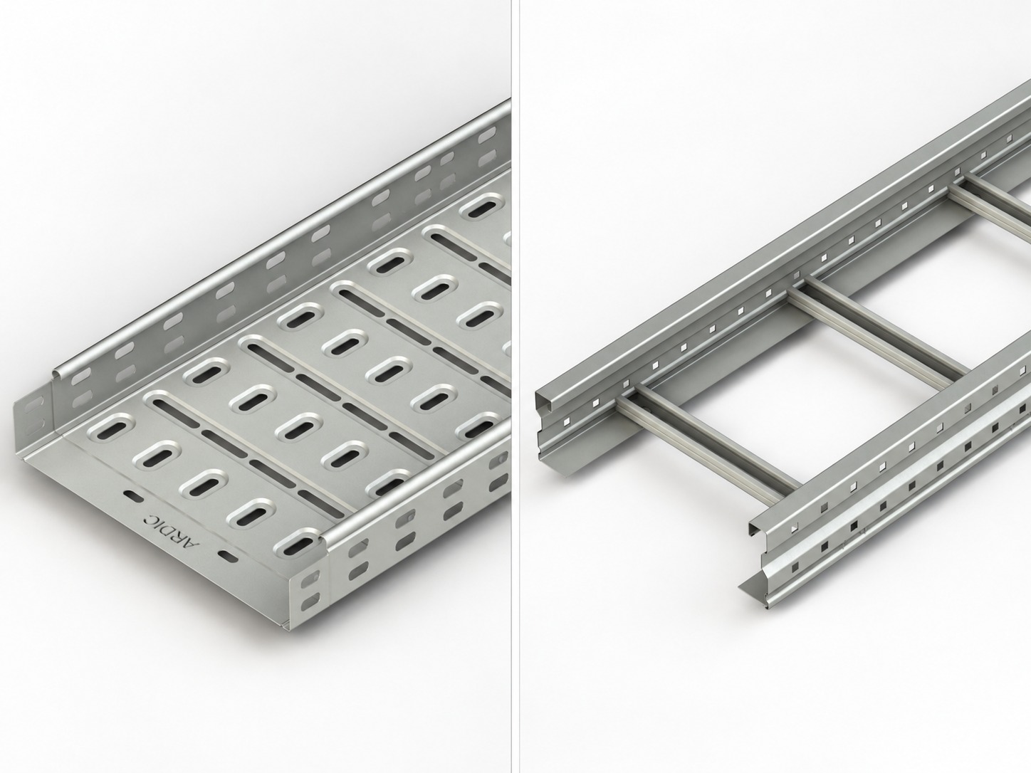
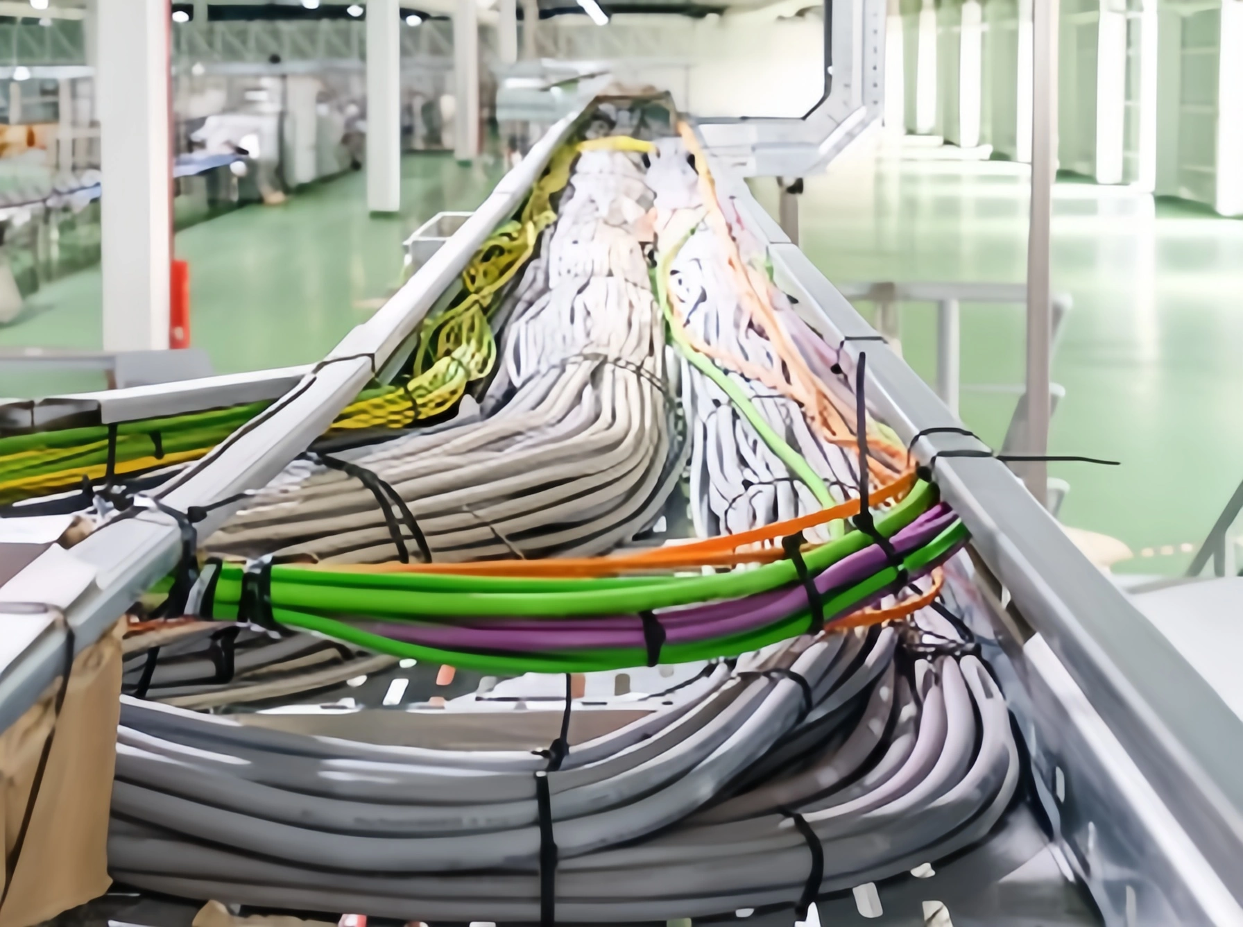
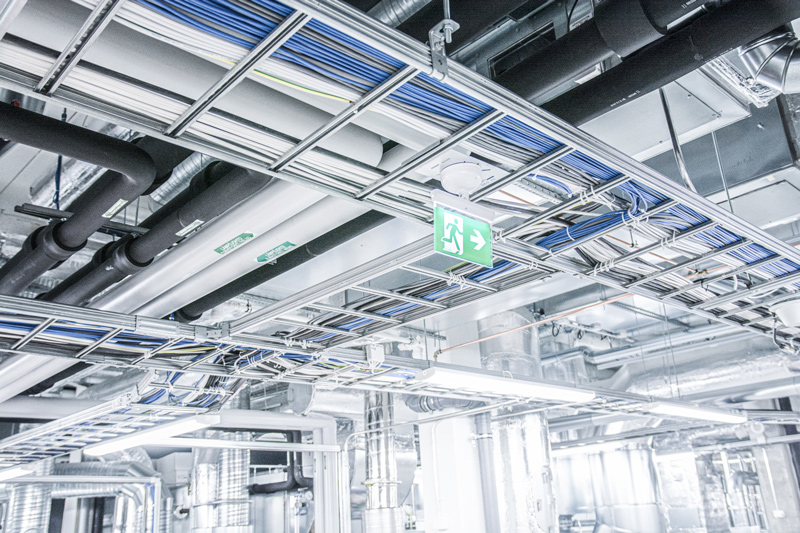
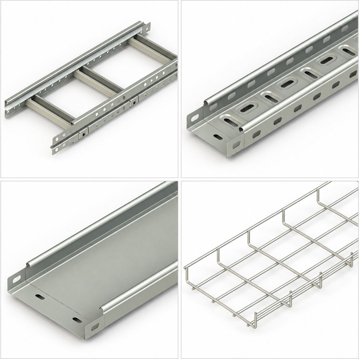
IEC describes IEC 61537:2023 as a standard specifying requirements and tests for cable tray and cable ladder systems that support and accommodate cables, and possibly other electrical equipment, in electrical or communication installations.[1] The systems may also arrange cables into groups. The scope excludes conduit, cable trunking, cable ducting and current-carrying parts.
That boundary matters. A cable tray or ladder supports cables; it is not automatically an enclosure, circuit conductor, fire barrier or seismic restraint system. The standard provides a product-system assessment framework, while a project still needs route design, cable loading, support engineering, environmental selection and installation controls.
The word system is equally important. A meaningful declaration relates to identified lengths, fittings, joints, supports or other components and the instructions that make them work together. A category page for cable trays or cable ladder systems can help you explore forms, but it is not conformity evidence.
Why the edition and national adoption matter
The official IEC page identifies IEC 61537:2023 as edition 3.0, published on 24 January 2023. It cancels and replaces the second edition from 2006 and constitutes a technical revision.[1] IEC lists significant changes that include revised corrosion classification, revised safe working load test types and procedures, new tests for different vertical mounting and running orientations, support-device tests, and revised annexes including tray use as a protective earth conductor.
Do not treat a report to IEC 61537:2006 as if it were automatically a report to IEC 61537:2023. The IEC page for the second edition shows a withdrawal date of 24 January 2023.[2] An IECEE test report form published in 2020 also states expressly that it applies to IEC 61537:2006.[3] These dates make edition checking a practical submittal task, not a footnote.
National and regional adoptions can follow their own timetable. CEN-CENELEC explains that a published European Standard must be given national-standard status by its members, while conflicting national standards are withdrawn.[4] That general process does not identify the applicable document for a particular project. The specification must identify the adoption, edition, amendments and jurisdiction.
Record all four items in the review log:
- standard designation and year;
- national or regional adoption, if applicable;
- amendments or project modifications;
- report edition and publication date.
Read classifications as a product profile
Classification is not a single badge. It is a structured description of characteristics and declared conditions. The exact 2023 requirements and categories must come from the licensed current standard and applicable project documents.
For procurement, translate each classification into three questions:
- What is declared? Capture the value, class, range or characteristic exactly.
- What configuration does it cover? Identify catalogue references, materials, dimensions, joints, fittings and supports.
- What evidence supports it? Link the declaration to a dated report, certificate or technical file under the correct edition.
Avoid combining separate attributes into an invented overall class. Mechanical capacity does not prove corrosion suitability. Electrical continuity does not establish structural capacity. A flame-related classification does not create an E30, E60 or E90 circuit-integrity rating.
Understand mechanical tests and tested configurations
Mechanical results only make sense when you know the test arrangement. IEC’s public summary confirms revised SWL procedures and added tests for specific orientations and support devices in the 2023 edition.[1] Therefore, a reviewer should never reduce the evidence to one load number.
A tested configuration should identify, as applicable:
- exact tray or ladder reference, material, finish, width and side height;
- length pieces, couplers, splice locations, fittings and fasteners;
- support type, span or support distance, and number of spans;
- joint position relative to supports and loading zones;
- horizontal or vertical mounting and running orientation;
- loading method, load distribution and any concentrated load;
- conditioning, temperature or environmental limitations;
- measurement positions, acceptance criteria and observed results.
These details determine whether the report represents the proposed installation. A straight multi-span run does not automatically cover a single span, riser, bend, tee or reducer. A tray-length test does not necessarily qualify a cantilever, pendant, C-shaped ceiling support or trapeze assembly.
Ask how the supplier extends a tested result across a product family. The answer should be a documented grouping rule, engineering rationale or test programme—not an assumption that similar appearance means equal performance. Include the load capacity guide as route-design context, while keeping current test documentation as the acceptance basis.
Keep SWL, test load and deflection separate
Safe working load (SWL) is a declared working limit for a defined system configuration and support arrangement. It is not the same as the load applied during testing, the load at failure, or the total cable mass on an entire route.
Keep these quantities in separate fields:
- SWL: the declared permissible working load under stated conditions;
- applied test load: the load placed on the specimen during a test stage;
- failure or ultimate load: a distinct result, if determined and reported;
- deflection: measured displacement at identified locations and loads;
- concentrated load: a localized action, unlike a distributed cable load;
- self-weight: weight of the tray, ladder, covers and accessories;
- support reaction: force transferred into brackets, hangers, anchors or structure.
Units require the same discipline. A mass line load in kilograms per metre is not a force line load in newtons per metre. Where a conversion is needed, use:
q = μ × g
Here, q is force per unit length in N/m, μ is mass per unit length in kg/m, and g is the acceleration due to gravity used by the project. State the value of g and the rounding method. Do not relabel kg/m as N/m or assume a test report’s units.
A load table should pair each SWL with the corresponding span, configuration and limitations. It should also report deflection information clearly enough for the designer to check serviceability. The cable tray weight calculation guide can help organize route inputs, but calculated cable mass still needs conversion and comparison with the correct documented capacity.
Finally, check every applicable load case. Cable weight, future allowance, covers, attachments, local equipment, installation activity and environmental actions may not all be represented by the declared SWL. Support reactions and anchorage remain separate design checks.
Review electrical, environmental and fire-related evidence
Mechanical capacity is only one part of the review. The current IEC summary names revised corrosion classification and an annex concerning tray use as a protective earth conductor.[1] Treat those topics as evidence prompts, not permission to make broad claims.
For metallic systems, confirm whether electrical continuity is declared and how joints, fittings, coatings and bonding components were represented. If the tray is proposed as a protective earth conductor, obtain the applicable design basis, test evidence, conductor calculations, fault requirements and local wiring-rule acceptance. A continuity result alone does not prove that every installed route can serve that function.
For environmental suitability, document material, coating or grade, temperature range, moisture, salinity, chemicals, UV exposure, impact, drainage and maintenance assumptions. Fittings, fasteners and supports need compatible evidence. Corrosion classes do not guarantee a fixed life, and IEC 61537 alone does not establish seismic performance.
Fire terminology needs particular care. Distinguish material reaction or flame propagation from circuit survival, fire resistance and the performance of cables, fixings and supporting construction as an installed assembly. Do not infer E30, E60 or E90 performance from an IEC 61537 reference.
Build a cable tray submittal package
A useful submittal lets a reviewer connect the specified route to the tested and declared system without guesswork.
Document and submittal checklist
- [ ] Cover sheet listing project, package, supplier, system families and revision.
- [ ] Compliance matrix quoting each project requirement and pointing to evidence.
- [ ] Applicable IEC edition, national adoption, amendments and deviations.
- [ ] Manufacturer literature with unambiguous catalogue references and dimensions.
- [ ] Bill of materials covering lengths, fittings, joints, covers, supports and fasteners.
- [ ] Drawings showing spans, support types, joint locations, orientation and special details.
- [ ] SWL tables linking load, span, exact configuration, units and limitations.
- [ ] Test reports with laboratory identity, dates, specimen details, methods and results.
- [ ] Deflection records and measurement locations at relevant load stages.
- [ ] Separate evidence for fittings, support devices and concentrated loads where required.
- [ ] Material, finish, corrosion, temperature and environmental declarations.
- [ ] Electrical continuity, bonding or non-conductivity evidence as applicable.
- [ ] Fire-related declarations using precise, limited terminology.
- [ ] Installation, cutting, repair, jointing, torque, bonding and maintenance instructions.
- [ ] Schedule of exclusions, substitutions, untested extrapolations and open actions.
Review reports for internal consistency. Product codes in a load table should match drawings and the bill of materials. Units should remain consistent. Photos should show enough detail to identify the specimen but should never substitute for a complete report.
Check installation assumptions before approval
Approval should capture the conditions that preserve the documented result. Put support spacing, joint-location rules, permitted orientations, compatible couplers, fastener requirements and support details on the approved drawings.
Coordinate route conditions that product testing does not settle: cable fill, thermal behaviour, access, drainage, building movement, wind, snow, ice, seismic restraint, anchors and structural reactions. Covers and accessories can change loads and environmental behaviour. At installation, verify labels, references, damage, support spacing, splices, fasteners, bonding and unauthorized modifications before cable pulling.
Avoid common documentation errors
- “Complies with IEC 61537” without an edition: request the year and adoption.
- One report for every product: compare the tested specimen with each proposed configuration.
- SWL without span: reject the orphan value; capacity needs its support arrangement.
- kg/m presented as N/m: retain mass and force as different quantities.
- Failure load used as working capacity: use the declared SWL under stated limits.
- Tray test used for supports or fittings: request component-specific evidence where applicable.
- Continuity treated as earthing approval: coordinate the full protective-conductor design.
- Flame language promoted to circuit integrity: require separate system evidence.
- Catalogue pages treated as certificates: use them for selection, not proof.
Frequently asked questions
Concise answers for reviewing IEC 61537 documentation.
No. IEC 61537 specifies requirements and tests; it does not itself issue a product certificate. Check whether the evidence is a declaration, laboratory report or certification document, then verify its scope and edition.
Not automatically. The 2023 edition technically revises the 2006 edition, so the reviewer must compare the project requirement, national adoption, report scope and relevant changes before deciding acceptance.
No. An SWL belongs to a stated configuration and support arrangement. Compare span, joints, orientation, load distribution, components, limits and units alongside the value.
No broad inference is justified. Seismic restraint and circuit-integrity or fire-resistance performance depend on separate project rules, evidence and the complete installed assembly.
Start with an edition-specific compliance matrix tied to exact catalogue references. It should lead to load tables, reports, classifications, drawings and installation instructions for the proposed system.
Conclusion
IEC 61537:2023 creates a common framework for cable tray and ladder system characteristics and testing, but a standard number alone is not an approval. Confirm the edition, reconstruct the tested configuration, separate SWL from other loads and deflection, and trace every classification to evidence. Then preserve those assumptions in drawings, supports and installation records.
For a project-specific review of route requirements and documentation needs, contact Ardıç Elektrik.
Sources
[1] https://webstore.iec.ch/en/publication/31963 — IEC 61537:2023, official publication page and public scope/change summary
[2] https://webstore.iec.ch/en/publication/5551 — IEC 61537:2006, official withdrawn second-edition page
[3] https://webstore.iec.ch/en/publication/66775 — IECEE TRF 61537B:2020, official page identifying IEC 61537:2006 as its basis
[4] https://www.cencenelec.eu/european-standardization/european-standards/ — CEN-CENELEC, European Standards and national adoption process