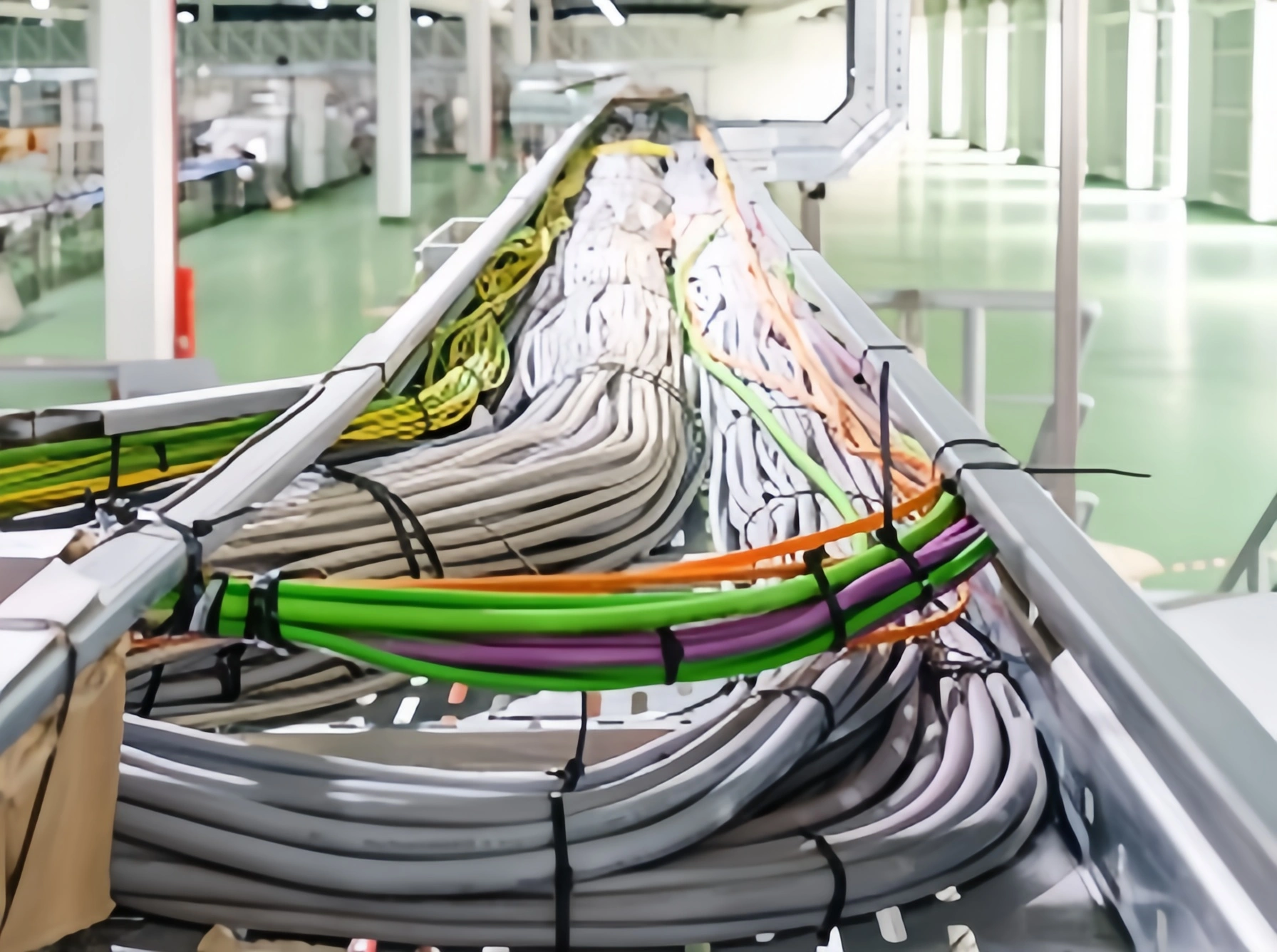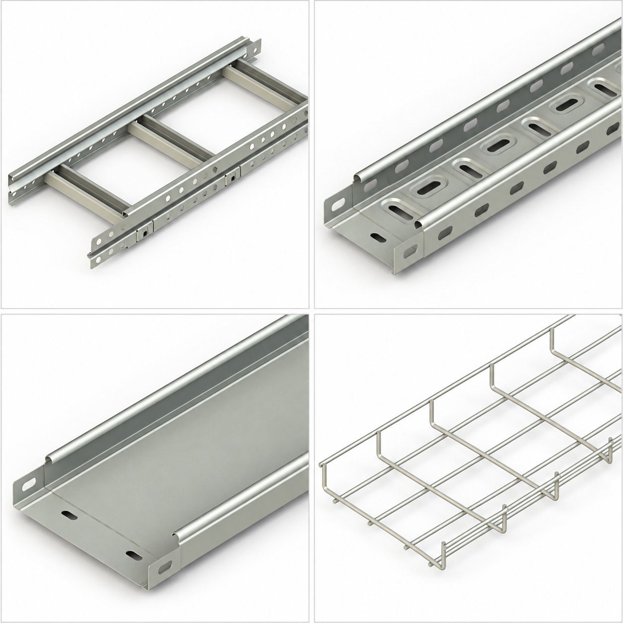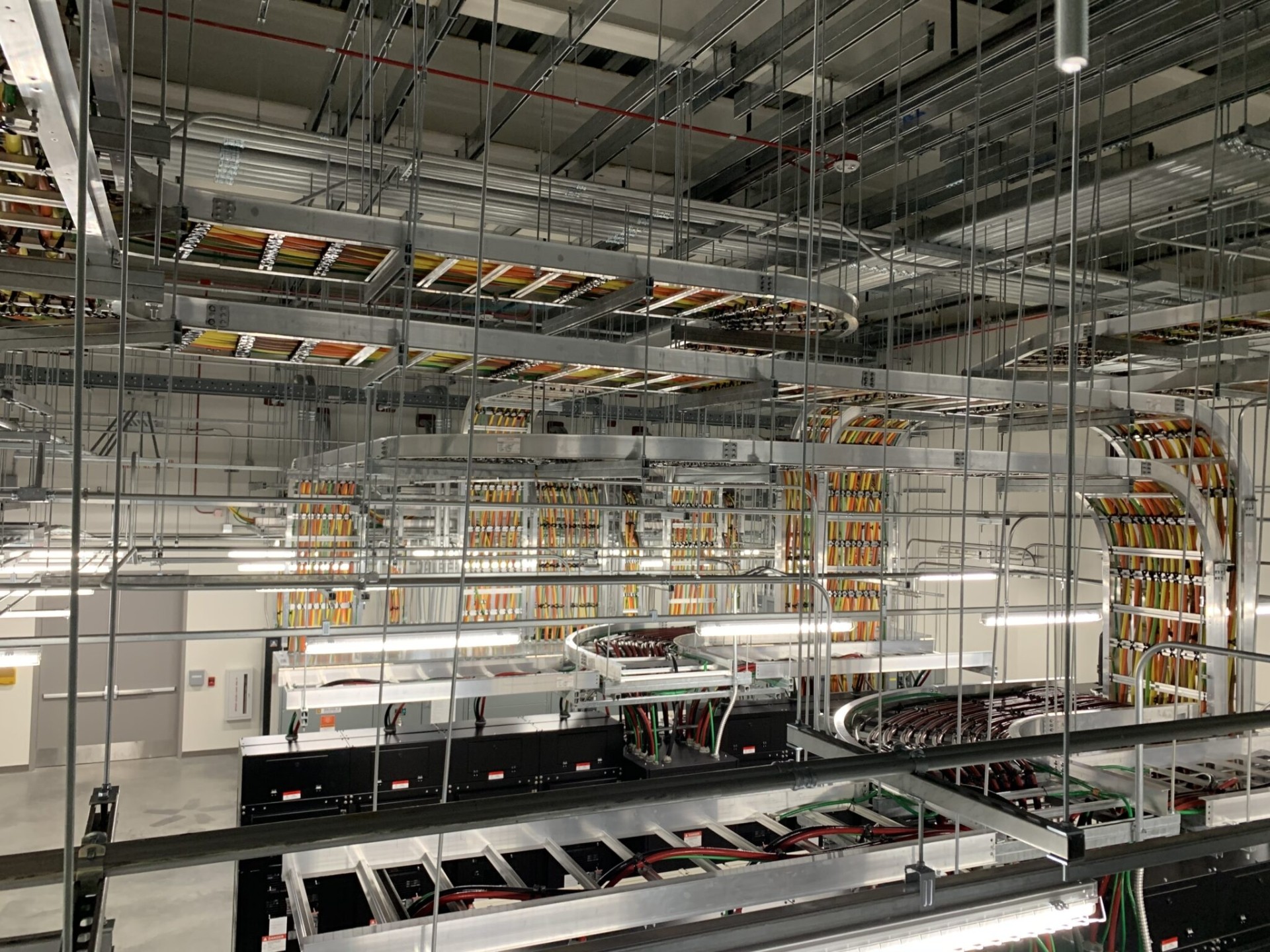


Cable Tray Support Spacing, Load Capacity and Deflection
A cable tray can carry the right cable quantity yet still deflect too much between supports. A sound cable tray load capacity check therefore connects three items: the design load, the tested safe working load (SWL), and the support arrangement used for that rating.
This guide explains how to build a preliminary load, read manufacturer tables without mixing test methods, evaluate deflection, and document support spacing. It does not prescribe a universal span or load. Final selection requires current data for the exact tray system and review by the project’s responsible engineer.
Table of contents
- Why load capacity and span belong together
- SWL, test load, failure, and deflection
- Build the design load in consistent units
- What changes a tray rating
- How to select support spacing
- Joints, fittings, and special route conditions
- Hypothetical preliminary load example
- Submittal and site verification checklist
- Common mistakes
- Frequently asked questions
- Conclusion
Why load capacity and span belong together
A tray rating is not a stand-alone number. It applies to a stated product configuration, span, support setup, loading pattern, joint arrangement, orientation, and test method. Increasing the distance between supports generally makes a straight section work harder and increases deflection, so a value from one span cannot be transferred automatically to another.
Published product data demonstrates this relationship. One Legrand product sheet presents safe load and deflection together across multiple support spans for one identified series.[5] Those values are product-specific evidence, not values for ARDIC products or for cable tray generally.
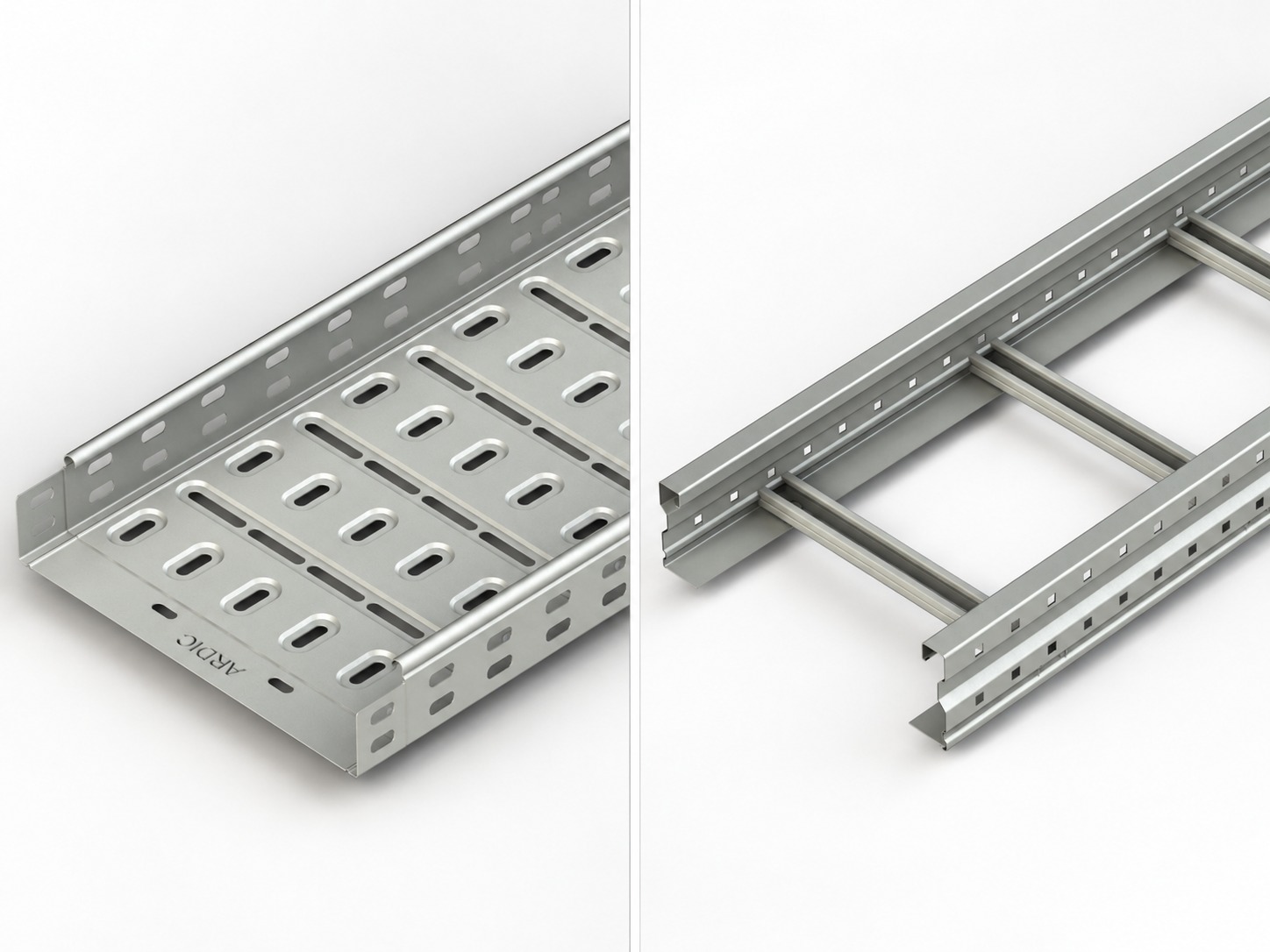
The same caution applies when comparing cable trays with cable ladder. Compare only configurations supported by traceable manufacturer data.
SWL, test load, failure, and deflection
Safe working load (SWL) is the load a manufacturer declares safe for a defined configuration under a stated standard or test procedure. The declaration should identify units, support span, relevant setup, and any restrictions. SWL is not simply the load that happened to be present when a specimen broke.
A test load is the load applied during verification. It may exceed the declared working load because the procedure is checking a specified performance condition or reserve. A failure or collapse load marks a different event. You should not divide or multiply one of these values by an assumed factor unless the governing standard and product documentation explicitly support that method.
Deflection is displacement under load. Longitudinal deflection describes movement along the span; transverse deflection concerns movement across the tray width. Deflection is a serviceability issue even when the system has not collapsed. Excess movement can affect appearance, clearances, couplings, cable support, drainage, or coordination with nearby services.
IEC lists IEC 61537:2023 as the international standard specifying requirements and tests for cable tray and cable ladder systems. Its official summary identifies revised SWL procedures and added tests for several mounting orientations and support devices.[1]
NEMA lists VE 1-2017 for metal cable tray systems, while its current installation guide is NEMA BI 50016-2024 (VE2).[2][3]
The Cable Tray Institute likewise distinguishes manufacturing and performance requirements in VE 1 from installation guidance in VE 2.[4]
Build the design load in consistent units
Start with a route-segment cable schedule. Cable populations change at branches, equipment drops, and future connection points, so one average for an entire project can conceal the controlling segment.
Keep these load components separate before combining them:
- installed cable linear mass;
- confirmed future cable linear mass;
- tray or ladder self-mass;
- covers, dividers, couplers, hold-downs, and other accessories;
- concentrated items that do not act as a uniform line load;
- installation loads, if permitted by the design basis; and
- environmental or accidental actions required for the location.
Cable data often arrives as linear mass, such as kg/m. Structural tables may use distributed force, such as N/m or kN/m. These are not the same quantity. Convert mass per unit length μ to distributed force q with:
q = μ × g
where g is gravitational acceleration. State the value used; this guide uses g = 9.81 m/s² in its hypothetical example. A value in kg/m should never be relabelled N/m without conversion.
Also separate a uniformly distributed load from a concentrated load. A junction box, cable drop, person, pulling force, or localized bundle may produce effects that a uniform-load table does not cover. Determine whether such loading is allowed, prohibited, or requires a separate calculation.
Environmental actions need a project-specific basis. Wind, snow, ice, seismic restraint, thermal expansion, vibration, and corrosion cannot be represented by one universal allowance. A mechanical SWL table does not establish other rated performance.
What changes a tray rating
Use the exact series identifier rather than a generic description such as “heavy duty.” Capacity and deflection can depend on:
- material and mechanical properties;
- sheet or section thickness;
- tray width, side height, and load depth;
- perforation, corrugation, rung, or wire geometry;
- straight-section length and orientation;
- span and support bearing arrangement;
- splice type and joint position;
- fittings, reducers, and field modifications;
- covers, dividers, and attachment methods; and
- test standard, test type, and reporting convention.
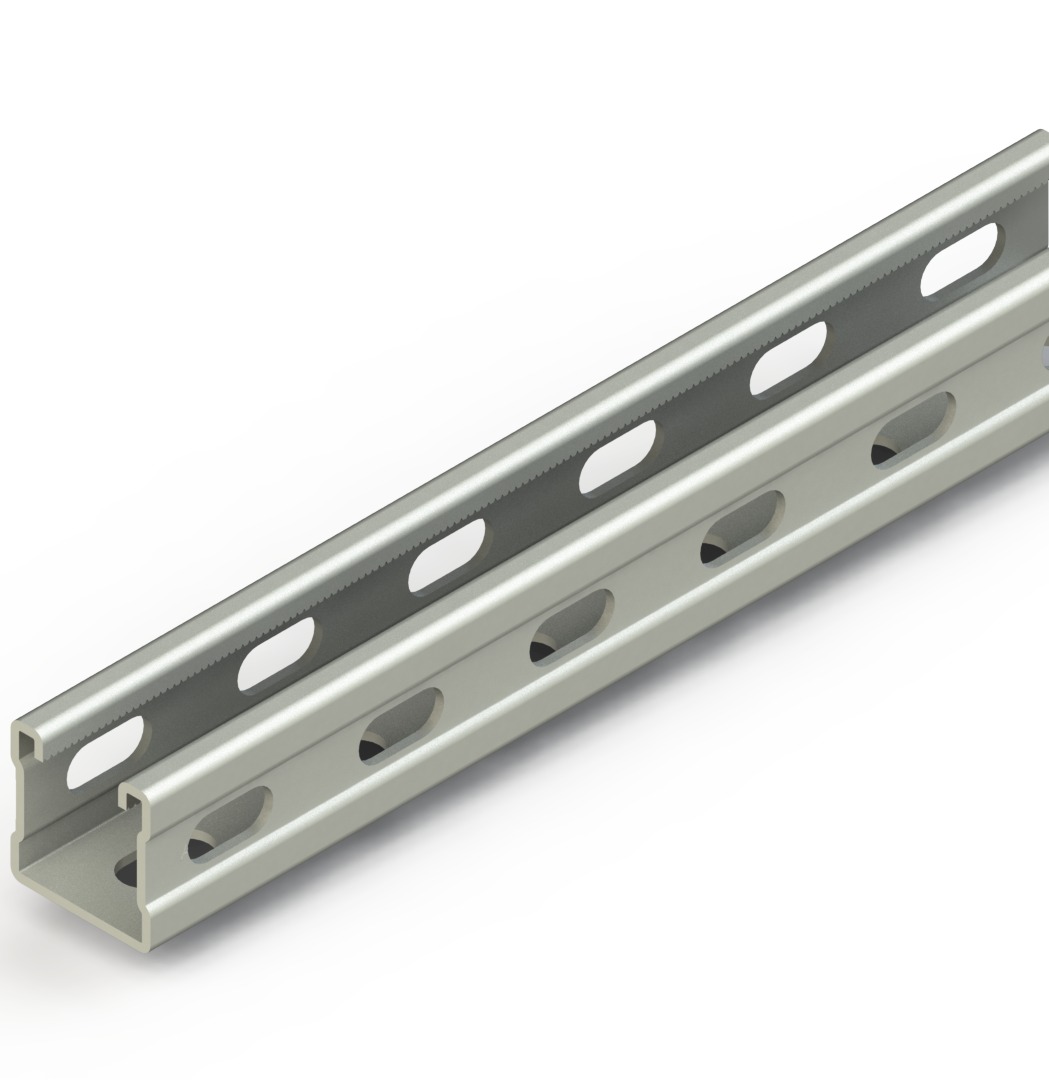
The support assembly is part of the load path. Cantilever brackets, trapezes, C-profiles, threaded rods, anchors, fasteners, and the building structure must each carry the applicable reactions. A strong tray on an inadequately selected bracket is not a strong system. Review the C-profile range and wider supporting systems as coordination categories, then verify every component against current project-specific data.
Coatings, material names, width, and side height alone do not establish SWL. Require evidence that matches the ordered construction.
How to select support spacing
Treat spacing as an output of coordinated design, not a rule of thumb.
- Define each route segment. Mark straight runs, bends, tees, reducers, risers, expansion locations, and equipment interfaces.
- Calculate the preliminary loads. Keep mass and force units explicit, and keep uniform, concentrated, and environmental actions separate.
- Identify the exact system. Record series, type, material, thickness, width, side height, splice, fittings, and accessories.
- Obtain current manufacturer data. Find the declared SWL and deflection for candidate spans under the applicable test method.
- Check both strength and serviceability. Confirm that the design load is within the declared working load and that predicted or reported deflection meets the project criterion.
- Verify the complete support path. Check brackets, channels, rods, anchors, fasteners, and supporting structure for their actual geometry and reactions.
- Coordinate installation details. Place supports and joints only as permitted by product instructions and the project design.
- Record the decision. Put the selected maximum spacing, configuration, load basis, document revision, and exceptions on drawings or schedules.
Shortening a span may improve straight-section behaviour, but it does not automatically validate a splice, fitting, bracket, anchor, or altered installation. Conversely, a long-span rating does not mean every accessory in that family can use the same spacing.
Joints, fittings, and special route conditions
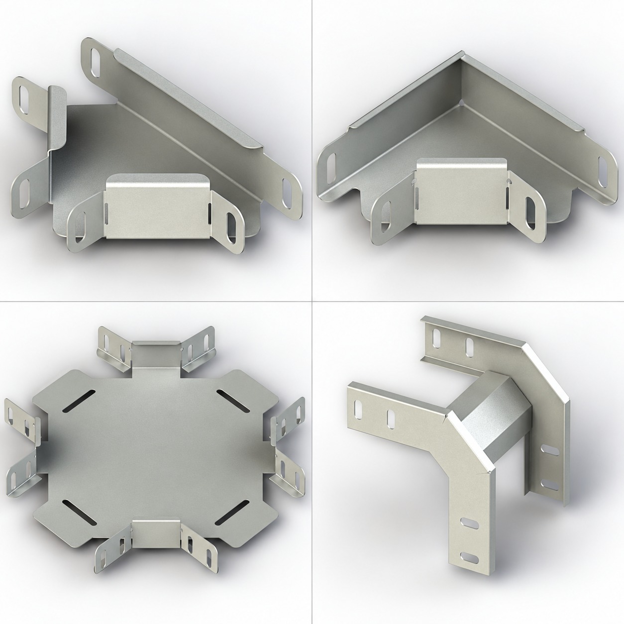
Straight-section tables do not automatically cover every fitting. Bends, tees, crosses, reducers, vertical transitions, and drop-outs change geometry and load transfer. Support them according to the manufacturer’s documented arrangement and the engineered route layout.
Joint position can also affect results. Some test methods define where couplings sit relative to supports, and product guidance may restrict that position. Never relocate a support or splice merely to match a generic detail from another series.
Check nonstandard orientation separately. Side-mounted, edgewise, vertical, or sloping runs can load components differently from a horizontal run. IEC’s official summary notes that its 2023 edition added tests for multiple vertical mounting and running arrangements, illustrating why orientation belongs in the declared configuration.[1]
For field cuts and site-formed fittings, confirm edge treatment, connectors, corrosion protection, bonding, cable restraint, and nearby supports. Do not assume an improvised fitting retains the straight-section rating.
Hypothetical preliminary load example
The following example is hypothetical and educational. It is not an ARDIC product specification, a support-spacing recommendation, or a final structural design.
Suppose one straight route segment has:
- 18 cables at
1.80 kg/meach; - 10 cables at
0.85 kg/meach; - tray self-mass of
6.20 kg/m; - cover mass of
2.40 kg/m; and - divider and distributed accessory mass of
0.90 kg/m.
First calculate installed cable mass:
μ_cables = (18 × 1.80) + (10 × 0.85) = 40.90 kg/m
Keep non-cable items visible, then combine the distributed masses:
μ_total = 40.90 + 6.20 + 2.40 + 0.90 = 50.40 kg/m
Using the stated g = 9.81 m/s²:
q_preliminary = 50.40 kg/m × 9.81 m/s² = 494.42 N/m ≈ 0.494 kN/m
If the documented future scope adds six of the 1.80 kg/m cables, their added mass is 10.80 kg/m. The revised total becomes 61.20 kg/m, or:
q_future = 61.20 × 9.81 = 600.37 N/m ≈ 0.600 kN/m
This is only a preliminary uniformly distributed gravity load. It excludes any concentrated, installation, wind, snow, ice, seismic, thermal, and accidental actions. The engineer must compare the applicable design combination with a manufacturer table for the exact series, span, joints, supports, and test basis, then check deflection and every support component.
Submittal and site verification checklist
A useful technical submittal should identify:
- manufacturer and exact series or catalogue code;
- tray type, material, finish, thickness, width, and side height;
- straight length, fitting types, cover, dividers, and splice hardware;
- SWL table with load units, spans, deflection, and test standard;
- test arrangement, joint rules, orientation, and stated limitations;
- support type, bracket projection, channel, rods, anchors, and fasteners;
- design cable load, self-mass, accessories, future load, and separate actions;
- required project deflection criterion and governing load combinations; and
- document revision, approval status, and installation drawing reference.
On site, match delivered sections to the approved submittal. Measure support spacing and inspect brackets, anchors, joints, hardware, damage, cuts, covers, and unplanned cable additions before loading.
After installation, manage change: new cables add fill and mass, while covers alter dead load and environmental response.
Common mistakes
Using one spacing everywhere. Route geometry, configuration, loads, fittings, and supports vary.
Comparing kg/m directly with N/m. Convert linear mass to force with a stated value of g, then keep units consistent.
Treating collapse as SWL. Test load, failure load, declared SWL, and deflection answer different questions.
Ignoring self-mass and accessories. Cables are only one part of the distributed gravity load.
Checking only the tray. Supports, anchors, fasteners, and the base structure share its load path.
Generalizing another manufacturer’s table. Product-specific data can illustrate method, but it cannot establish ARDIC series performance.
Frequently asked questions
Concise answers about SWL, deflection, load data, and support spacing.
SWL is the manufacturer-declared working load for a defined product configuration and test basis. Read it with the stated span, units, joint arrangement, orientation, and limitations; do not treat it as a universal property of the tray category.
There is no universal support spacing for every system. Select spacing from the exact manufacturer’s load-and-deflection data, then verify fittings, joints, brackets, anchors, environmental actions, and the supporting structure.
No. Deflection is displacement under load and is commonly a serviceability concern. Failure or collapse is a different condition, while SWL and test load depend on the stated test method.
Yes, but keep it separate from cable mass and other additions before combining compatible distributed loads. Confirm how the manufacturer’s table treats tray self-weight so you do not omit or double-count it.
Not for final selection. A table must match the relevant series, material, thickness, width, side height, span, joints, support arrangement, orientation, fittings, and test method.
Conclusion
Cable tray support spacing is inseparable from load and deflection. Build a unit-consistent design load, distinguish SWL from test and failure loads, and match the result to current data for the exact system. Then verify joints, fittings, supports, anchors, and the structure rather than checking the tray alone.
For project-specific product coordination, send the route layout, cable schedule, design actions, candidate spans, environment, and required documentation through ARDIC’s contact page.
A traceable load basis and a configuration-specific support schedule turn a rough tray layout into a design that can be checked, installed, and maintained.
Sources
[2] NEMA VE 1-2017 Metal Cable Tray Systems — NEMA
[3] NEMA BI 50016-2024 (VE2) Cable Tray Installation Guidelines — NEMA
[4] Codes and Standards — Cable Tray Institute
[5] 1D82 steel cable tray safe-load and deflection data — Legrand