

Cable Tray Selection for Solar PV Plants
A solar PV plant route is not simply a place to put cables. It sits between the array layout, the cable schedule, the support structure, the site environment and future maintenance work. Cable tray selection for solar PV plants therefore begins with project inputs, not with a universal material or spacing rule. IEC 62548-1 covers PV-array design requirements including DC array wiring, protection devices, switching and earthing provisions; it does not turn a containment choice into a complete electrical design.[1]
This guide helps you:
- map the conditions that affect a route;
- separate containment decisions from PV electrical, structural and corrosion design; and
- prepare a reviewable submittal and maintenance record.
Table of contents
Start with a route-and-exposure map
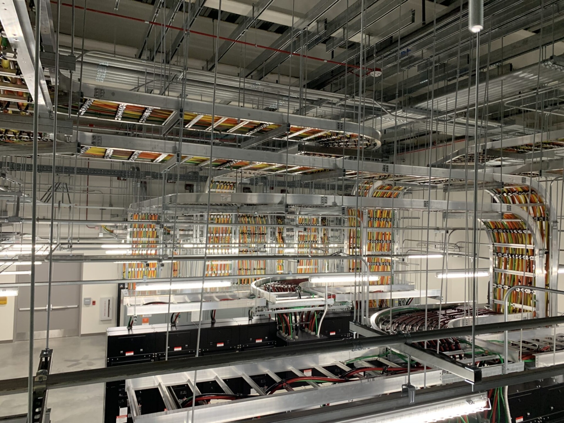
Treat the plant as a set of different exposure zones rather than one generic outdoor environment. A route beneath modules, a run across open ground, a transition near inverter equipment and a path inside an enclosure can face different combinations of sun, wind-driven moisture, dust, standing water, salt-bearing air, chemicals and mechanical activity. Document those zones on the drawings before selecting a tray or ladder series.
The map should also identify where cable routes cross structure, roads, drainage paths, fencing, equipment pads and maintenance corridors. Note where a route changes elevation, enters equipment, passes a field joint or needs a cover. These observations do not prescribe a product. They give the designer and reviewer a shared record of conditions that the selected system must address.
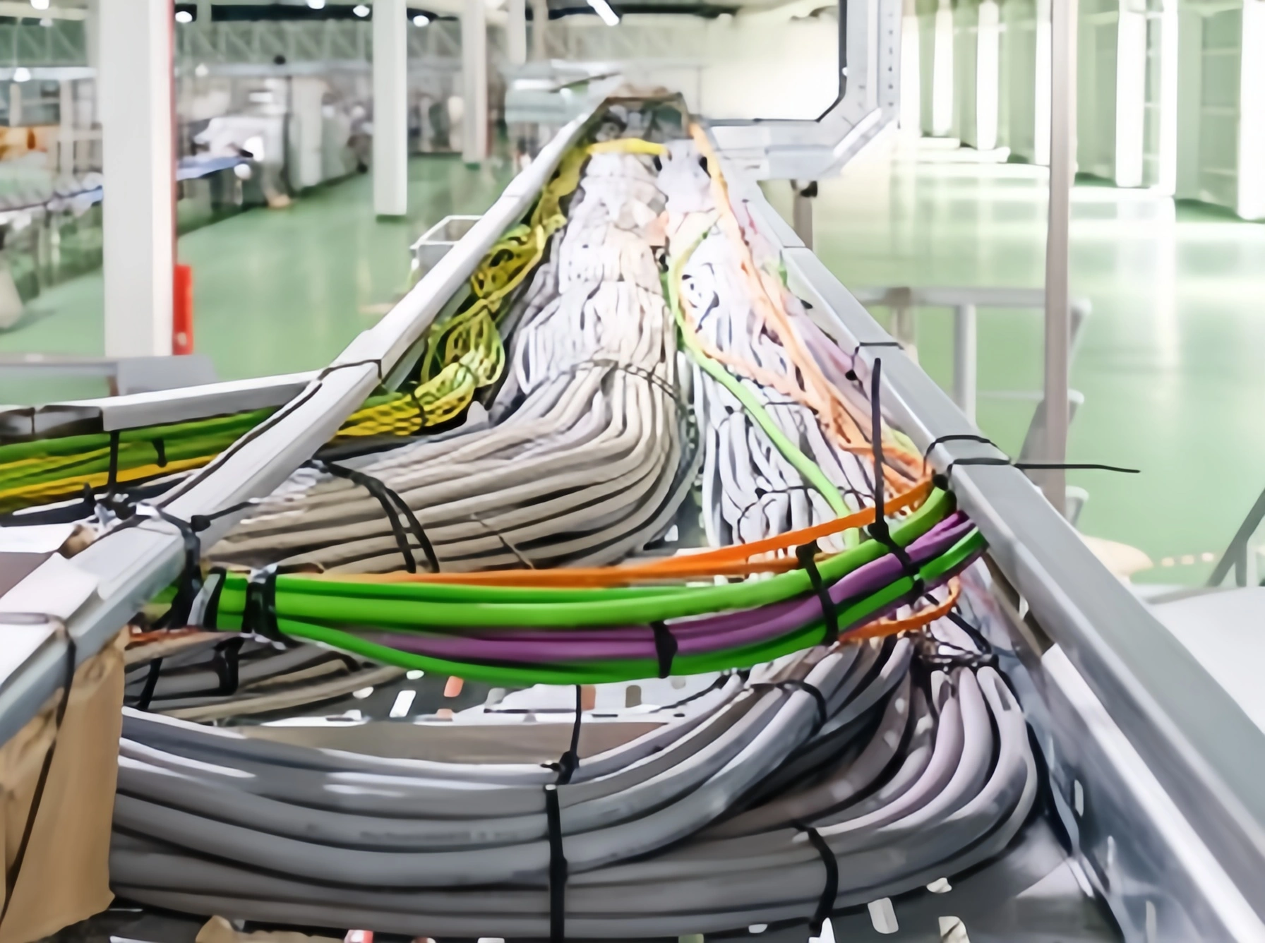
The cable schedule belongs beside this map. Record each circuit’s cable type, diameter range, manufacturer installation information, voltage class, function and entry or termination points. DC string wiring, AC collection circuits, communications and control circuits may have different documentation needs. Do not infer separation, containment fill or allowable bend details from a generic PV layout; use applicable rules, the project documents and cable manufacturer information.
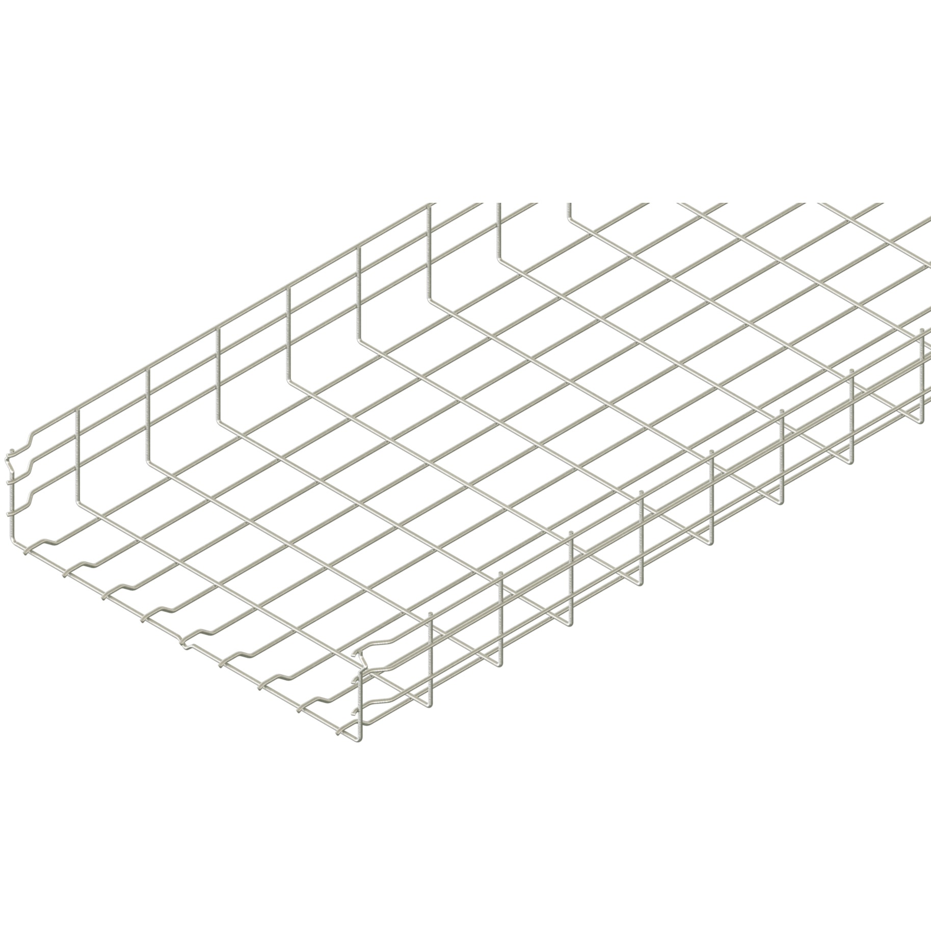
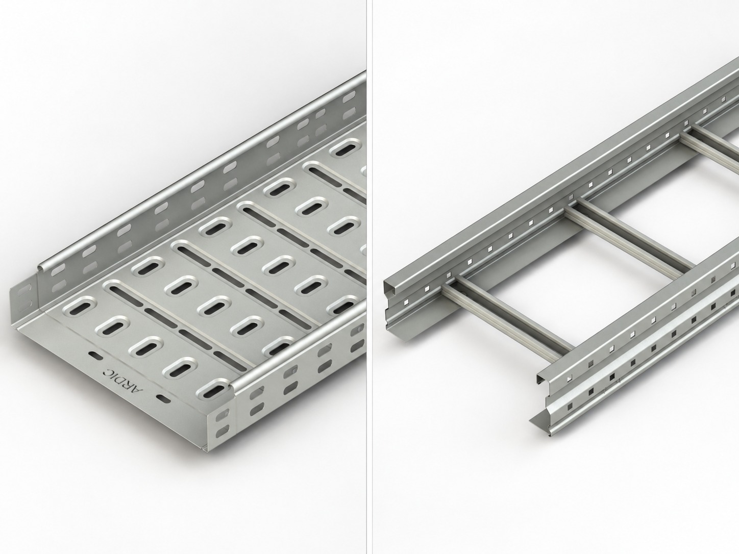
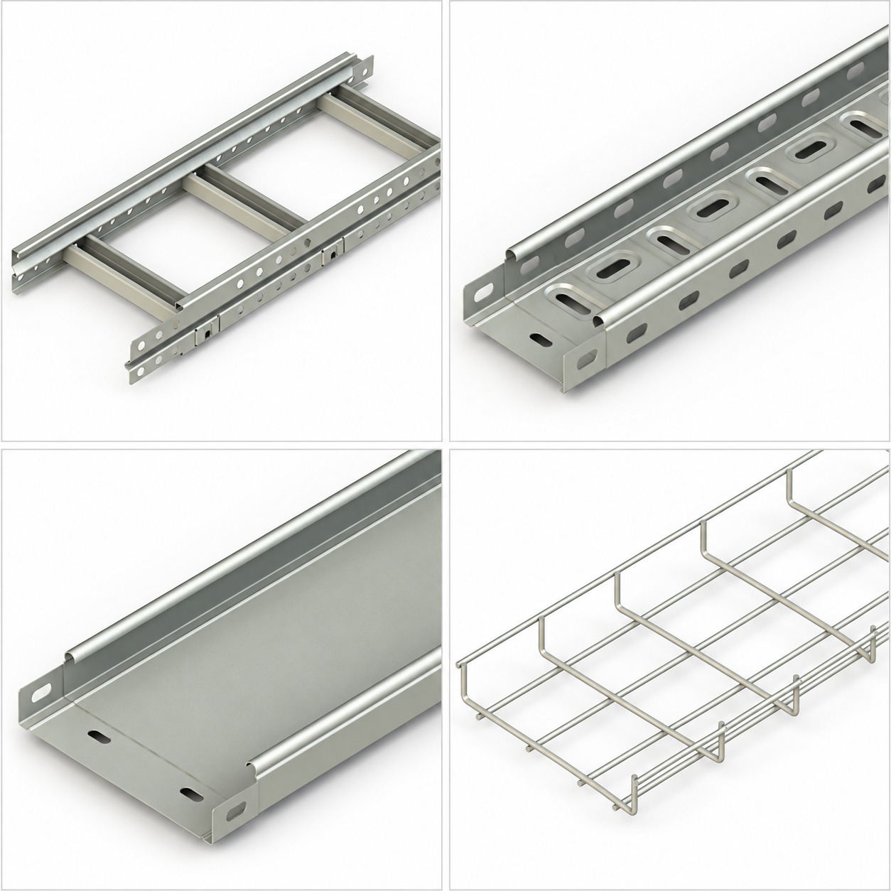
For a starting point, compare route alternatives with the relevant cable tray systems and record why each route remains accessible. The link is a product-category reference, not evidence that a particular product is suitable for the plant.
Coordinate containment with the PV electrical design
Cable containment supports routing and protection from foreseeable mechanical contact; it does not independently define electrical safety, system earthing, lightning protection, overcurrent protection or isolation. The design team should coordinate the route with the single-line diagram, layout drawings, cable schedule, equipment documentation and the local requirements that govern the project.
IEC describes the scope of IEC 62548-1 as PV-array design, including DC array wiring, protection, switching and earthing provisions.[1] Use that boundary constructively. Ask the electrical designer to identify the circuits, interfaces and required records that affect the route. Then ask the containment review to show how the proposed tray path, fittings, cable entries and support interfaces align with those inputs.
A useful coordination sheet names an owner for each decision:
- The electrical designer confirms circuit function, routing constraints, protective arrangements and applicable standards.
- The structural designer confirms the supporting structure and attachment approach.
- The corrosion or materials review evaluates the site exposure and material interfaces.
- The installer confirms that the documented route can be assembled, inspected and maintained as drawn.
- The owner or operator confirms access, isolation and records needed for future work.
This approach avoids a common mistake: treating a tray as a substitute for an electrical design decision. It also makes changes visible. If cable type, route, equipment position or support structure changes, reopen the coordination sheet instead of assuming the original selection still applies.
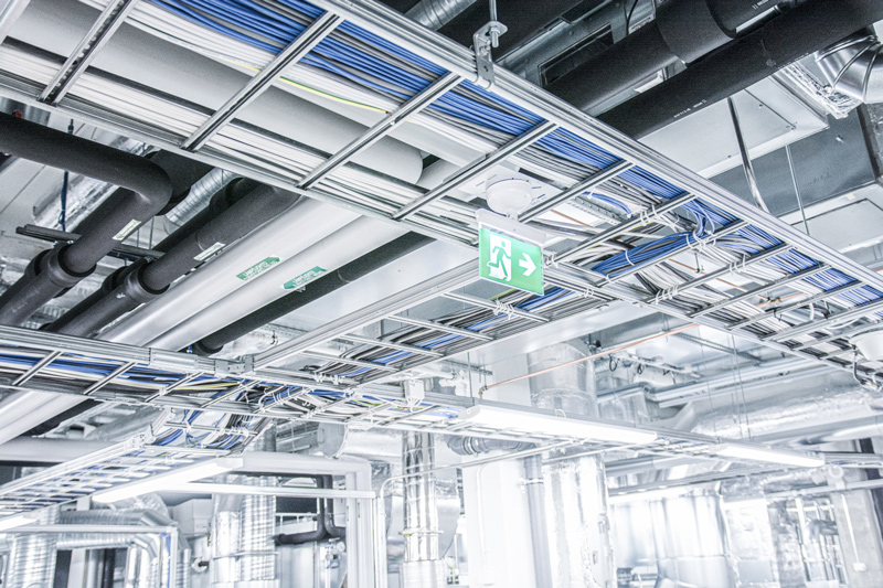
Where a route needs an open rung arrangement, examine the available cable ladder options only after the project team has defined the route constraints. Selection remains subject to current series documentation and qualified review.
Assess materials and interfaces without preset answers
PV sites can combine ultraviolet exposure, heat, moisture, dust, salts, cleaning residues and dissimilar materials. Those inputs can matter to cable supports, coatings, fasteners, joints and interfaces, but their relevance depends on the actual location and assembly. Treat the combined environment as a documented project input rather than reducing the assessment to one condition.
That approach supports an exposure-based review, not a universal material recommendation. Describe the site geography and operating environment, obtain any available environmental or corrosion assessment, and compare it with current manufacturer documentation for the proposed tray, fittings, fasteners and support hardware. Identify interfaces with mounting structures, concrete, grounding components, roofs, enclosures and other metals. A qualified reviewer can then determine what details require isolation, protection, inspection or a different assembly.
Avoid shorthand such as “outdoor equals one finish” or “coastal equals one metal.” Those statements skip the conditions that drive a project decision. Use a matrix instead: list exposure zone, proposed components, interfaces, evidence reviewed, open questions and decision owner. The materials and finishes guide can help frame terminology, but it is not a site-specific corrosion-life assessment.
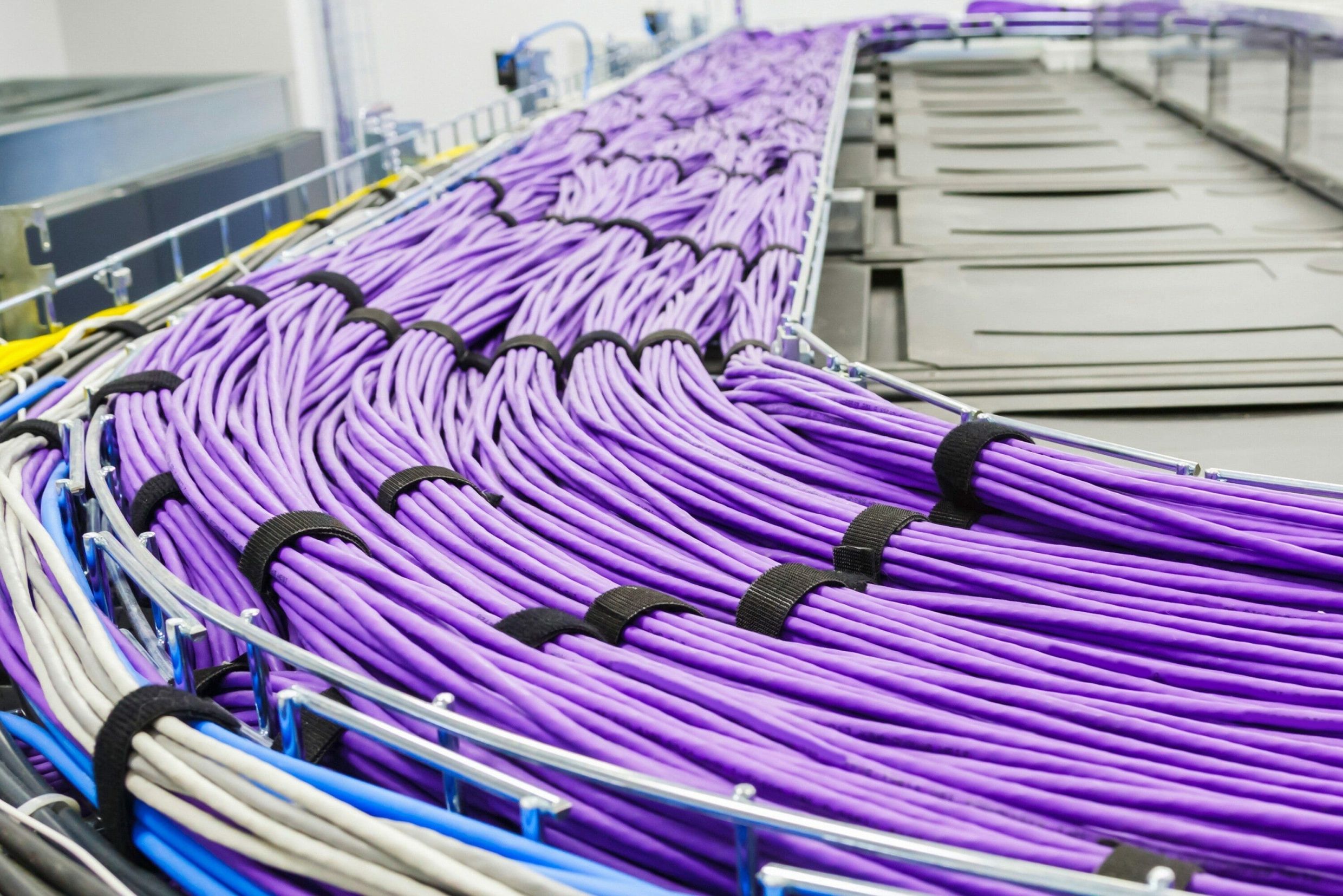
Cable compatibility also needs direct review. Confirm cable manufacturer requirements for support, securement, bend handling, temperature and outdoor exposure. The cable, not the tray alone, defines important handling limits. Keep manufacturer documents with the submittal so field teams do not replace controlled information with memory.
Design drainage, geometry and support interfaces
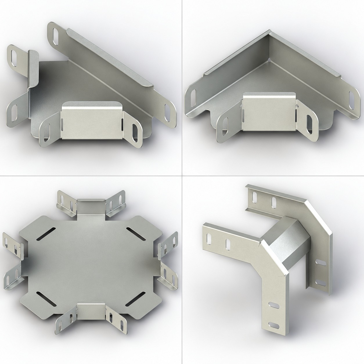
Route geometry should make inspection and cable installation practical without imposing a one-size-fits-all arrangement. Review transitions, changes in elevation, branch points, entries into equipment, cable exits, expansion or movement interfaces and locations where debris or water could collect. If the project proposes covers, side protection or other accessories, identify their purpose and the conditions they are intended to address.
Drainage deserves its own drawing review. Do not assume that an outdoor route drains adequately because it is elevated or perforated. Check the actual route slope, local obstructions, crossings, equipment foundations and planned cleaning approach. Coordinate with civil and structural teams when drainage channels, grading or access roads affect the route. The review should record how the selected arrangement avoids creating inaccessible collection points, while leaving final details to the project design.
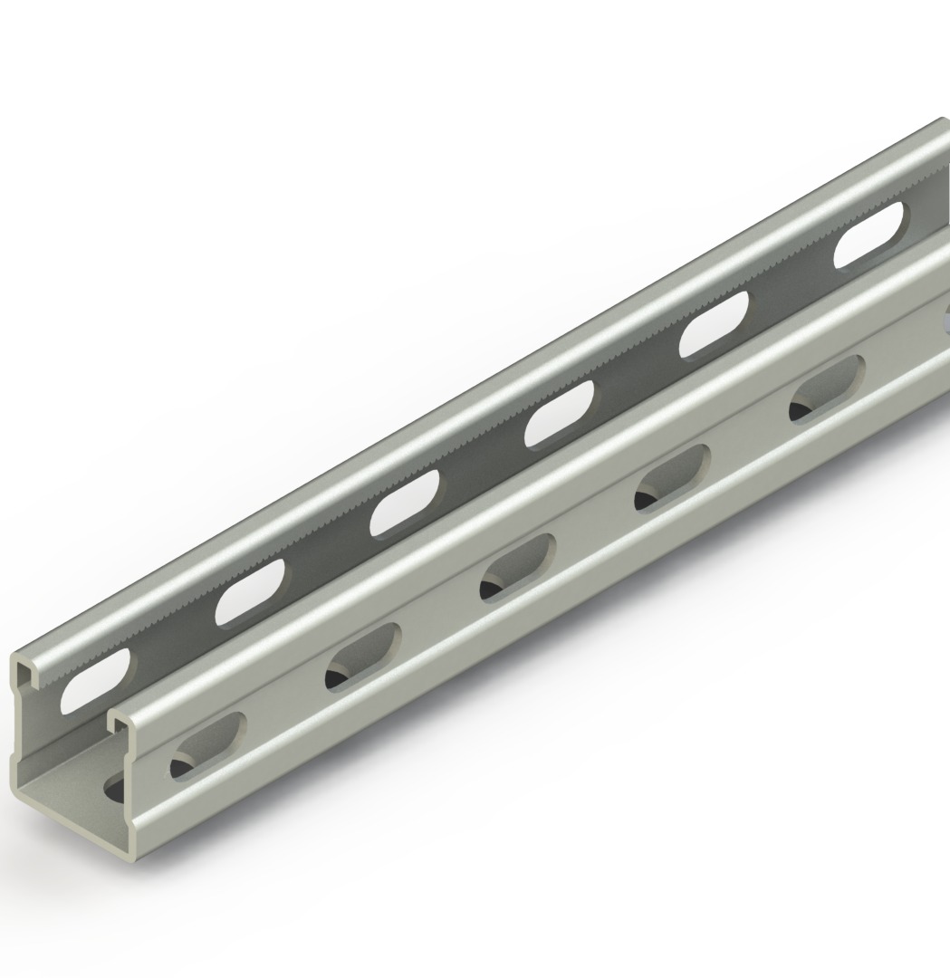
Support design is also a separate discipline. Loads, spans, fastening, deflection, wind effects, seismic provisions and attachment capacity depend on the selected system, route and structure. Do not copy a spacing value from another plant. Use the current manufacturer data for the specified series together with the structural design and applicable local requirements. The supporting systems overview is a useful catalogue reference, not a substitute for those calculations or approvals.
At equipment boundaries, show the interface clearly. A drawing should identify the containment termination, cable-entry method, bonding or earthing interface where applicable, clearance responsibility and party who verifies the final condition. This makes it easier to distinguish a cable-management detail from the wider PV electrical and protection design.
Build access and maintenance into the route
A route that can be installed but not inspected creates an avoidable lifecycle problem. Build access into the layout from the start: consider walkways, equipment doors, test points, vegetation control, cleaning access, safe work planning and the ability to trace a cable without dismantling unrelated work. The IEA PVPS O&M guidelines address PV power plants in different climates, which reinforces the need to make maintenance planning specific to the plant environment.[2]
Use an inspection plan that states what is observed, who observes it and what record is retained. Depending on the project, that plan may cover visible support condition, fasteners, covers, cable securement, debris, drainage, route damage, labels and changes around equipment entries. It should not claim that a visual inspection proves electrical, structural, lightning-protection or corrosion performance. Escalate those questions to the responsible qualified discipline.
Keep as-built drawings current. Mark route changes, equipment relocations, replacements and approved deviations. Link those records to cable schedules, approved submittals, manufacturer instructions and any test or commissioning records held by the project. A controlled record supports later troubleshooting without making unsupported predictions about yield, reliability or service life.
For safety planning, recognize that PV work requires an authorized project safety plan. The project’s isolation arrangements, work methods and local legal requirements govern the work; this article does not replace them.
Prepare a controlled selection record
A complete selection record turns a broad product choice into a reviewable project decision. Start with the current drawings and capture the assumptions that were actually checked. The package should be clear enough that a later reviewer can understand both the chosen route and the limits of the decision.
Include the following items:
- Route and exposure register: zone drawings, site conditions, route crossings, access points and drainage observations.
- Cable and equipment inputs: cable schedule, manufacturer documentation, equipment entry requirements and current layout references.
- Containment schedule: proposed tray or ladder series, fittings, covers, joints, fasteners and support interfaces, with current product documents attached.
- Discipline reviews: electrical, structural, materials/corrosion, safety and operations comments, including unresolved items and their owners.
- Installation and handover records: approved changes, inspection points, as-builts, maintenance instructions and traceability information.
Before release, test the record against a short set of questions. Does it distinguish containment from electrical, structural and corrosion design? Does it identify the source of every product-specific statement? Does it avoid universal values for fill, support spacing, materials or service life? Does it name the reviewer who can close each open technical issue?
If your project team needs product information for a documented PV route, use the Ardıç contact page to request current series documentation and discuss the project inputs with the appropriate technical reviewers.
Frequently asked questions
Concise answers for planning PV cable containment routes.