

What Is an E90 Cable System? A Functional-Integrity Guide
During a fire, not every cable route has the same duty. A project may require certain circuits to remain operational for a defined period to support safety functions such as fire alarm, smoke control, emergency lighting, or other life-safety services. In that setting, selecting a metal tray alone does not establish E90 functional integrity. The cables, containment, supports, fixings, connections, and installation arrangement must be evaluated as one documented system.
This guide explains E30, E60 and E90; the system approach used in DIN 4102-12; and the checks needed before specification or installation. A key boundary applies to Ardıç’s published FIRES document: it does not state that every Ardıç tray or ladder is E90. It classifies defined LINEAR 1 system configurations with specified PRAKAB cables and components.[2]
Contents
- What E30, E60 and E90 mean
- How an E90 system works
- What DIN 4102-12 covers
- Core components
- Design and selection checks
- E90 versus a general cable tray
- Typical uses and common mistakes
- Ardıç E90 cable management solutions
- Documentation and project verification
What E30, E60 and E90 mean
E30, E60 and E90 are functional-integrity designations used for an electrical cable system exposed to fire. The number denotes 30, 60 or 90 minutes of the stated functional-integrity classification. DIN 4102-12 addresses requirements and testing for circuit-integrity maintenance of electrical cable systems.[14] This is not a melting-temperature claim for steel, a reaction-to-fire class for a material, or a standalone statement about a cable sheath.
Keep three subjects separate:
- Reaction to fire describes how a material behaves when exposed to fire.
- Fire resistance can describe the performance of a building element under a specified fire exposure.
- Functional integrity of an electrical cable system concerns whether the tested system continues to perform its electrical function without the relevant failure during the classification period.
A cable marking therefore does not automatically classify a complete route. Equally, a galvanized or robust-looking tray is not E90 unless the complete assembly is supported by applicable evidence.
How an E90 system works
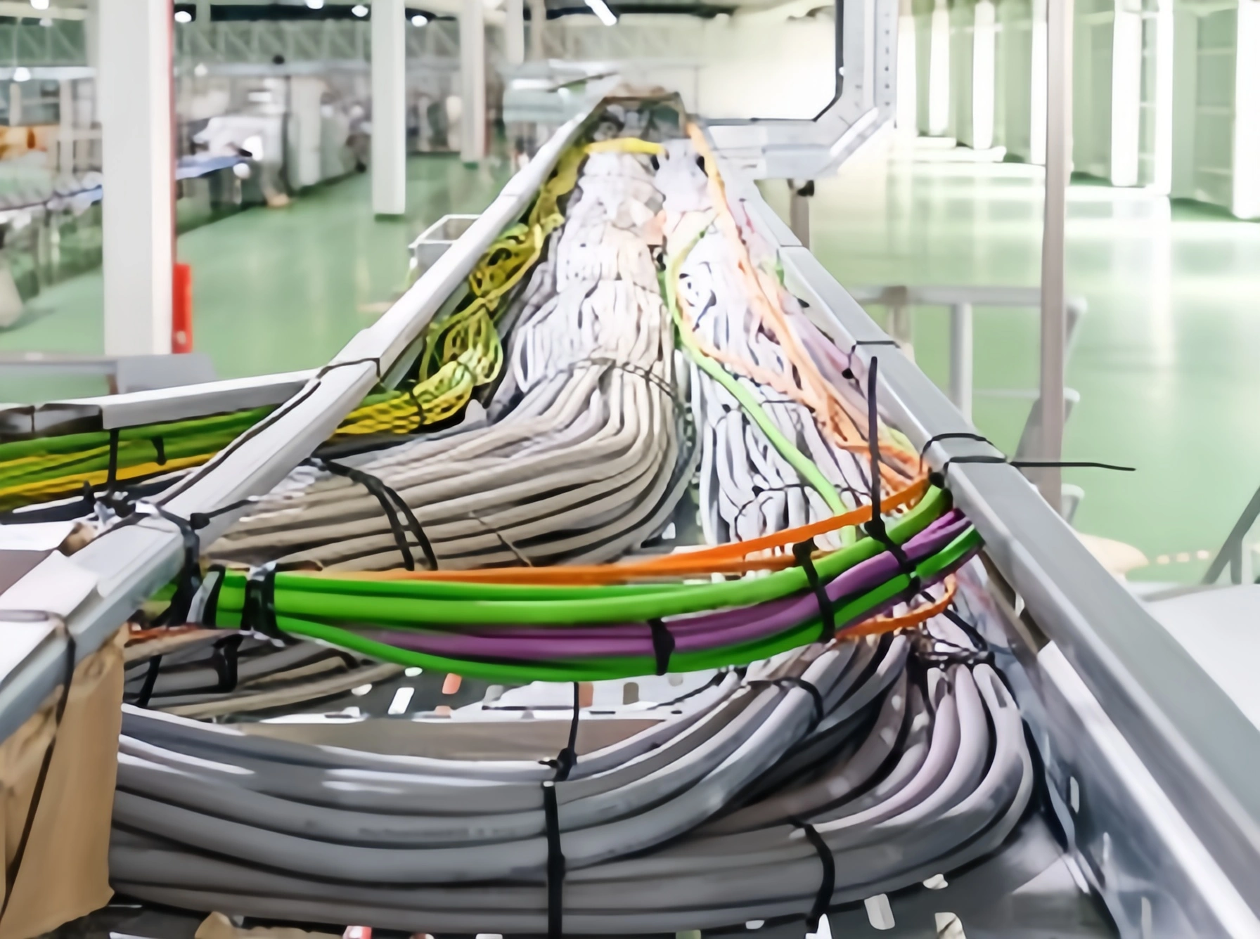
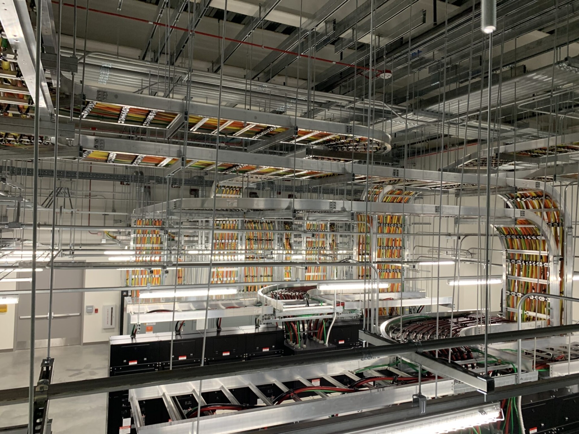
A functional-integrity cable management system is a coordinated load path and cable-retention arrangement. Under fire exposure, a cable may be affected if a support deforms, a fastening moves, a joint opens, or a cable slips or kinks at a change of direction. A straight tray section cannot be assessed in isolation.
Ardıç’s FIRES expert judgement report describes LINEAR 1 cable trays with accessories, consoles, brackets, supports, hangers and threaded rods together with PRAKAB halogen-free power and communication cables.[2] The classification is given for stated cable types and defined track arrangements. The document also shows that the result is not identical for every arrangement: one listed communication-cable configuration is classified E60, while others are E90.[2]
A sound project process brings together electrical design, fire strategy, structural support design and controlled installation. The electrical designer identifies required circuits; the fire strategy defines the required function period; the support design checks the load path; and the installation team preserves the documented configuration.
What DIN 4102-12 covers
The FIRES report gives its classification in accordance with DIN 4102-12:1998-11.[2] In this context, the focus is the functional integrity of an electrical cable system in fire. That system includes the cables and their route, support, fixing and connection arrangement.
Do not use the standard name as a generic catalogue label. The practical question is whether the classified configuration matches the project: cable type and construction, route orientation, tray and support geometry, load, fixing method and supporting construction. If it does not, the design team needs an appropriate technical assessment rather than an assumption.
The FIRES report states that it is not a type approval or certification of the product.[2] It also conditions validity on the product, field of application, standards and regulations not changing. This is why substitutions and site changes must be controlled.
Core components
The exact component list comes from the relevant report and drawings. In general, a functional-integrity system includes:
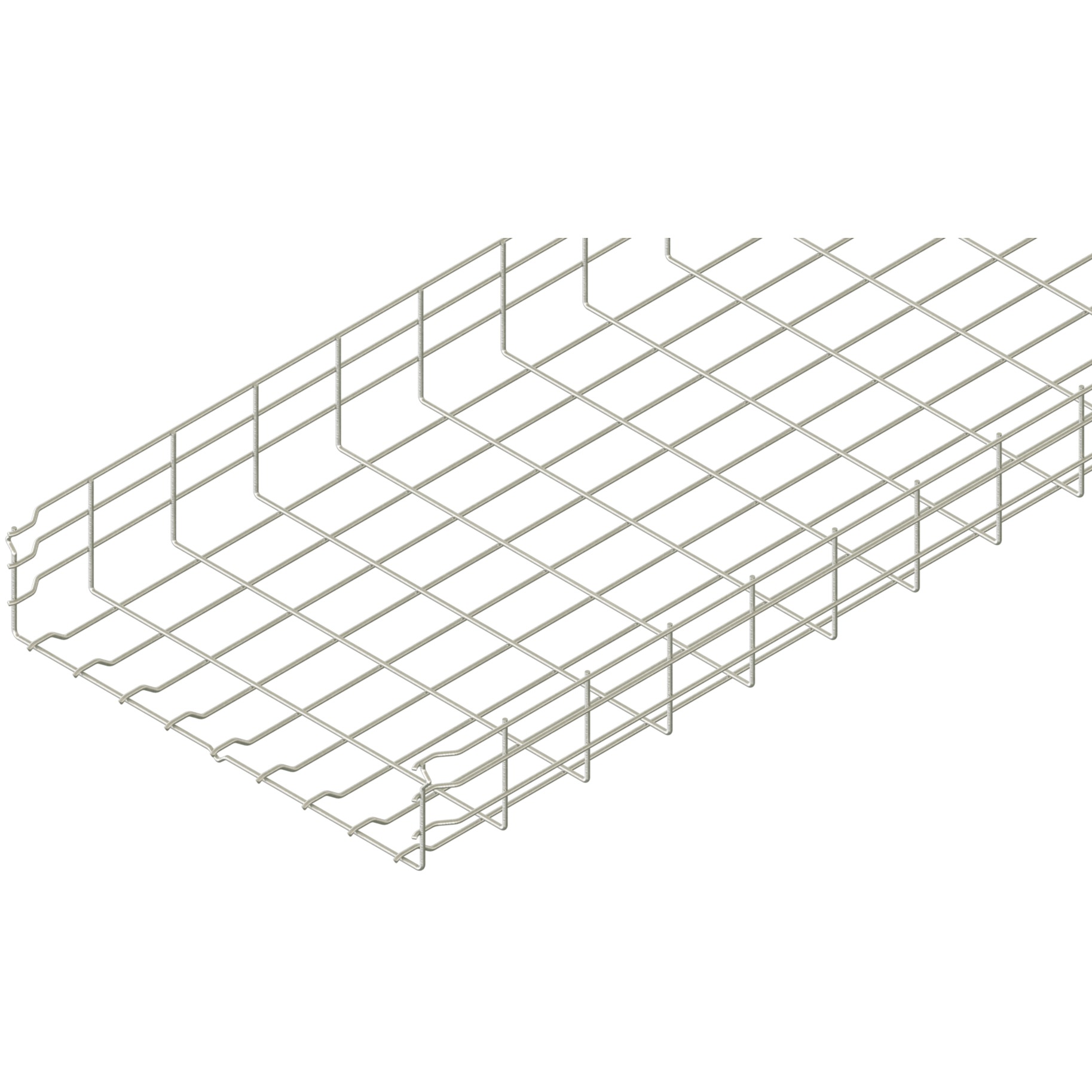
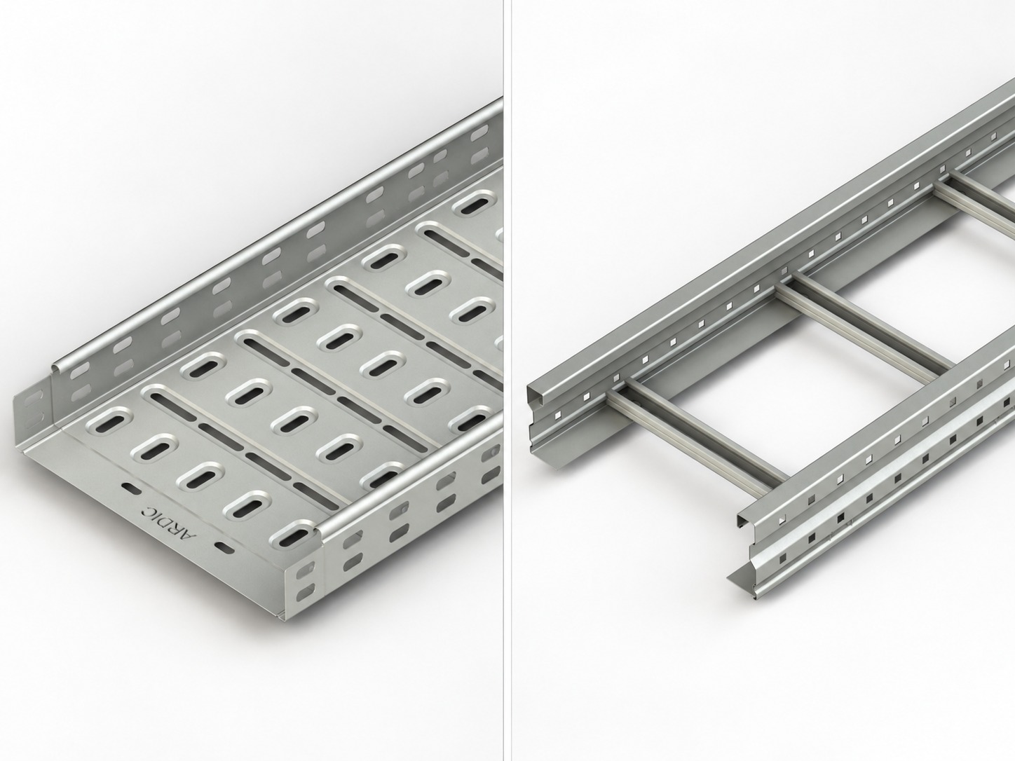
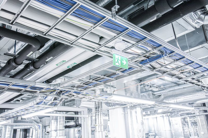
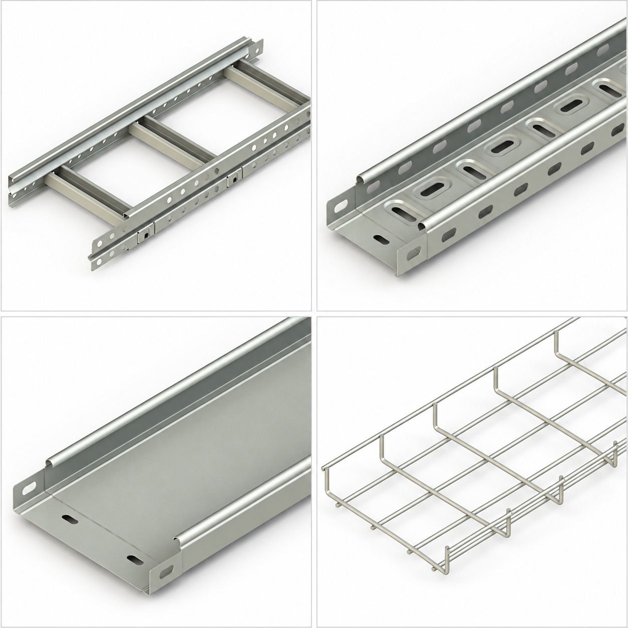
- Cable tray or cable ladder to support the cable route.
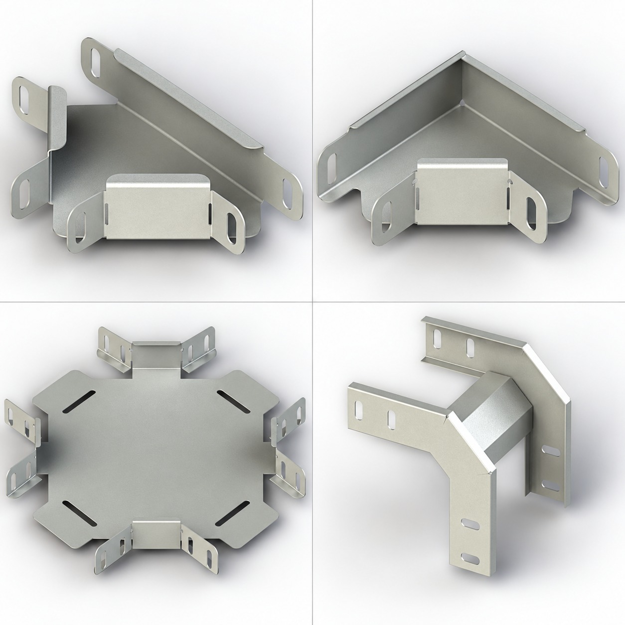
- Joints and connection parts to assemble straights, fittings and route changes.
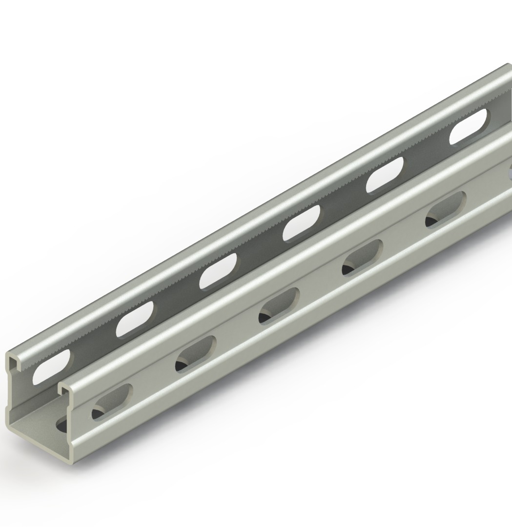
- Brackets, supports, hangers and threaded components to transfer system loads to the structure.
- Anchors and fixing elements as part of that complete load path.
- Cables and cable-retention details that match the classified cable family and arrangement.
- Covers or other accessories, only where the applicable document allows them.
The Ardıç FIRES report specifically concerns LINEAR 1 trays and defined accessories/support arrangements used with listed PRAFlaDur 90 and PRAFlaGuard F cables.[2] Ardıç’s wider Products range contains multiple cable tray and cable ladder families; it should not be described as a blanket E90 range.
Design and selection checks
Start by separating safety-related circuits in the cable schedule. Record the service, cable data, route, required functional-integrity class and applicable fire scenario. Then divide the route into horizontal runs, verticals, bends, transitions, penetrations and equipment approaches.
Compare the proposed installation against the classification document, item by item:
- Is the cable type and conductor configuration within the stated scope?
- Does the tray, connection method and support arrangement match the documented configuration?
- Is there an applicable arrangement for wall, ceiling or vertical installation?
- Are cable load, cover load and other relevant loads within the documented limits?
- Are threaded components, anchors and the supporting construction suitable for the required fire performance?
- Are transitions detailed so the cable will not slip or kink?
The FIRES report lists 1,200 mm support/profile spacing and stated cable loads for some LINEAR 1 classification rows.[2] Those values are not general design values for other Ardıç series, other cables, added covers, alternative supports or a different structural substrate. Use them only within the exact report scope and verify the applicable row.
The load-bearing construction used to fix the cable system must be demonstrated to have fire resistance at least equivalent to the classified functional-integrity class.[2] This does not mean that the FIRES report certifies the building structure; it requires the project team to verify that evidence separately.
A component substitution is a material change, even when a part looks compatible. A different fastener, anchor or cable may not exhibit the same performance under fire. Approved drawings, installation information and the full classification report should be part of the controlled work package. Ardıç’s cable tray installation guide provides useful general installation checks, but it does not replace the E90 configuration.[8]
E90 versus a general cable tray
| Topic | General cable tray or ladder | Classified E90 system arrangement |
|---|---|---|
| Unit of evaluation | Chosen product and project design | Defined combination of cable, containment, supports, fixing and installation |
| Fire claim | Does not itself prove functional integrity | Limited to the stated class and conditions |
| Cable selection | Based on electrical design and applicable rules | Must match the classified cable family and parameters |
| Supports | Designed for load, span and structure | Also checked against the classified/tested arrangement |
| Change control | Requires technical compatibility review | Can invalidate scope and needs explicit assessment |
| Evidence | Product data, drawings and calculations | Those items plus classification report and traceable installation record |
It is equally inaccurate to say that a general tray is inherently “not fire-resistant.” It simply does not automatically prove the E90 functional-integrity classification discussed here. Tray versus ladder selection still depends on cable mix, route, supports, environment and documented product data.[9]
Typical uses and common mistakes
Where required by the project or applicable regulations, functional-integrity systems can be evaluated for fire alarm, smoke-extraction control, emergency lighting, safety-related circuits and selected infrastructure or industrial functions. This is a typical use context, not a universal requirement that every emergency circuit or building needs E90.
Common errors include:
- selecting only the tray body and omitting cables and supports;
- replacing a documented component with a visually similar part;
- increasing support spacing or changing the arrangement for site convenience;
- treating cable load, covers and accessories as separate from the classified system;
- stating that an entire product series is E90 without reading the scope; and
- failing to record what was actually installed.
The FIRES report calls for marking that identifies the installer, system name, functional-integrity class and report number, actual mechanical cable load and assembly date.[2] Traceable labelling is useful for inspection, maintenance and later modifications.
Scope of Ardıç’s FIRES E90 classification
Ardıç publishes a Fires E90 document in its official Certificates section.[1] The full FIRES E90 classification report is an expert-judgement classification for an ARDIC ELEKTRIK LINEAR 1 cable system with stated PRAKAB power and communication cables under DIN 4102-12:1998-11.[2]
The accurate project statement is narrow: the report covers classified applications using the defined LINEAR 1 tray system, stated accessory/support configurations and listed PRAKAB cable combinations. Final selection depends on a technical match between the complete report scope and the proposed project arrangement.
Ardıç’s catalogues can help compare product codes, dimensions, materials, finishes and compatible accessories.[3] They should be read alongside the FIRES report. A catalogue by itself does not approve a particular E90 installation.
Documentation and project verification
Freeze a document set before procurement or installation:
- current project specification and fire strategy;
- cable schedule, cable manufacturer documentation and route drawings;
- the full FIRES report and relevant classification pages;
- selected LINEAR 1/accessory/support bill of materials;
- evidence for anchors and the supporting construction where required;
- installation, inspection, labelling and as-built record plan.
Bonding and protective-earthing arrangements also require project-specific design. A mechanical connection does not, by itself, prove the intended electrical continuity. Ardıç’s cable tray grounding guidance makes the same distinction between mechanical assembly and the approved electrical strategy.[17]
An E90 decision is therefore not a product-name decision. It is a documented system, controlled installation and traceable verification process. Once the route, cables and scope have been compared, contact Ardıç to discuss current product and documentation alignment for the project.
Sources
[1] https://www.ardic.com/en/certificates
[2] https://www.ardic.com/uploads/2026/04/fires-e90.PDF
[3] https://www.ardic.com/en/catalogs
[8] https://www.ardic.com/en/media-center/blog/cable-tray-installation-guide
[9] https://www.ardic.com/en/media-center/blog/cable-tray-vs-cable-ladder-selection
[14] https://dinmedia.de/en/standard/din-4102-12/5407466
[17] https://www.ardic.com/en/media-center/blog/how-is-cable-tray-grounding-done