

How to Select Heavy-Duty Cable Trays for Industrial Plants
Industrial plants often use the phrase “heavy duty” before the route, load unit and evidence have been defined. This guide shows how to select heavy-duty cable trays for industrial plants through route data, full load-unit control, test-boundary discipline, interface reviews and traceable handover records.
- Build a route-specific data sheet.
- Keep mass, force, reactions and test terms separate.
- Match evidence to the exact installed configuration.
Define the decision, not a universal rating
Heavy-duty cable trays for industrial plants are selected by evidence, not by a label. The term may signal that a route deserves closer mechanical, environmental, operational and documentation review, but it does not create a universal load, span, deflection, support-spacing, thickness, fill or cable-count rule. The defensible question is narrower: can one exact tray or ladder configuration, with its fittings and supports, be evaluated for one stated route and one controlled set of project inputs?
IEC 61537:2023 describes requirements and tests for cable tray and cable ladder systems intended to support and accommodate cables and, where applicable, other electrical equipment in electrical or communications installations.[1] That scope helps establish the containment boundary. It does not eliminate the need to check the project’s structural interfaces, cable data, environmental conditions, installation method and governing regulations.
Start by recording what “heavy-duty” is meant to solve on this route: high cable linear mass, concentrated equipment interfaces, difficult access, vibration exposure, a demanding atmosphere, frequent modifications, or a combination. A clear problem statement prevents a procurement shorthand from being mistaken for a verified project rating.
Build a route data sheet before choosing a system
A useful route data sheet follows the physical path rather than a generic product family. Break the route at changes in elevation, direction, support type, cable population, enclosure condition, room classification or environmental exposure. Each segment then has an owner, a drawing reference and a reviewable set of inputs.
- Route geometry: plan and elevation, straight runs, offsets, risers, crossings, penetrations, transitions and available maintenance clearances.
- Cable information: current schedule, outside diameters, linear masses, bend constraints, installation sequence, retention needs and foreseeable additions.
- Interfaces: steelwork or concrete attachment points, equipment entries, conduit transitions, expansion interfaces and any separate structural system.
- Operating context: access restrictions, cleaning, washdown, dust, chemicals, humidity, temperature exposure, vibration, impact risk and outage constraints.
Keep sources and revision dates with these inputs. Cable schedules often change after containment drawings are issued. A data sheet that identifies its design revision makes later change control possible. It also makes it easier for electrical, structural, process and maintenance reviewers to see which assumptions they own.
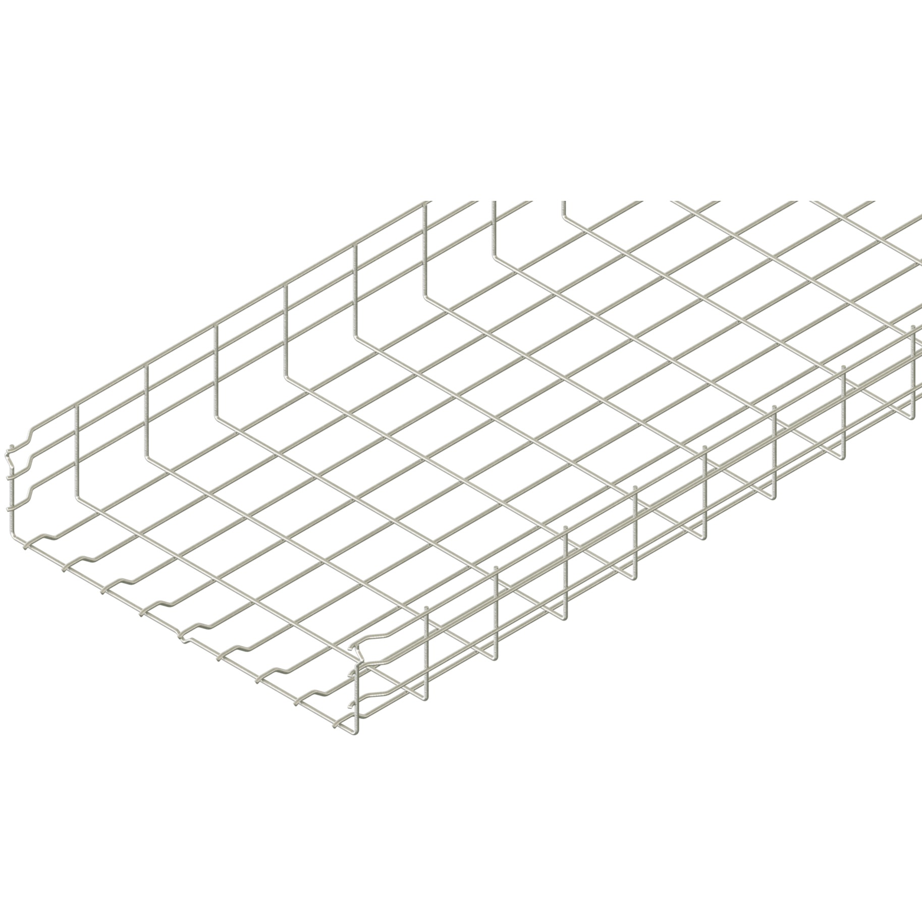
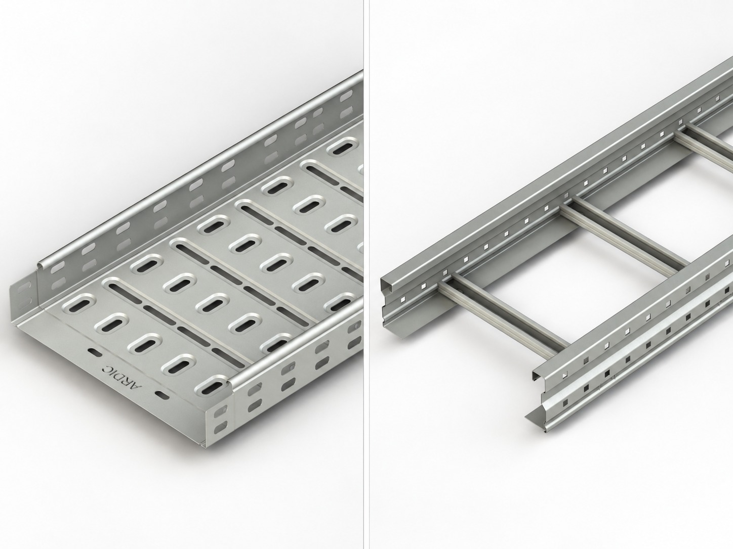
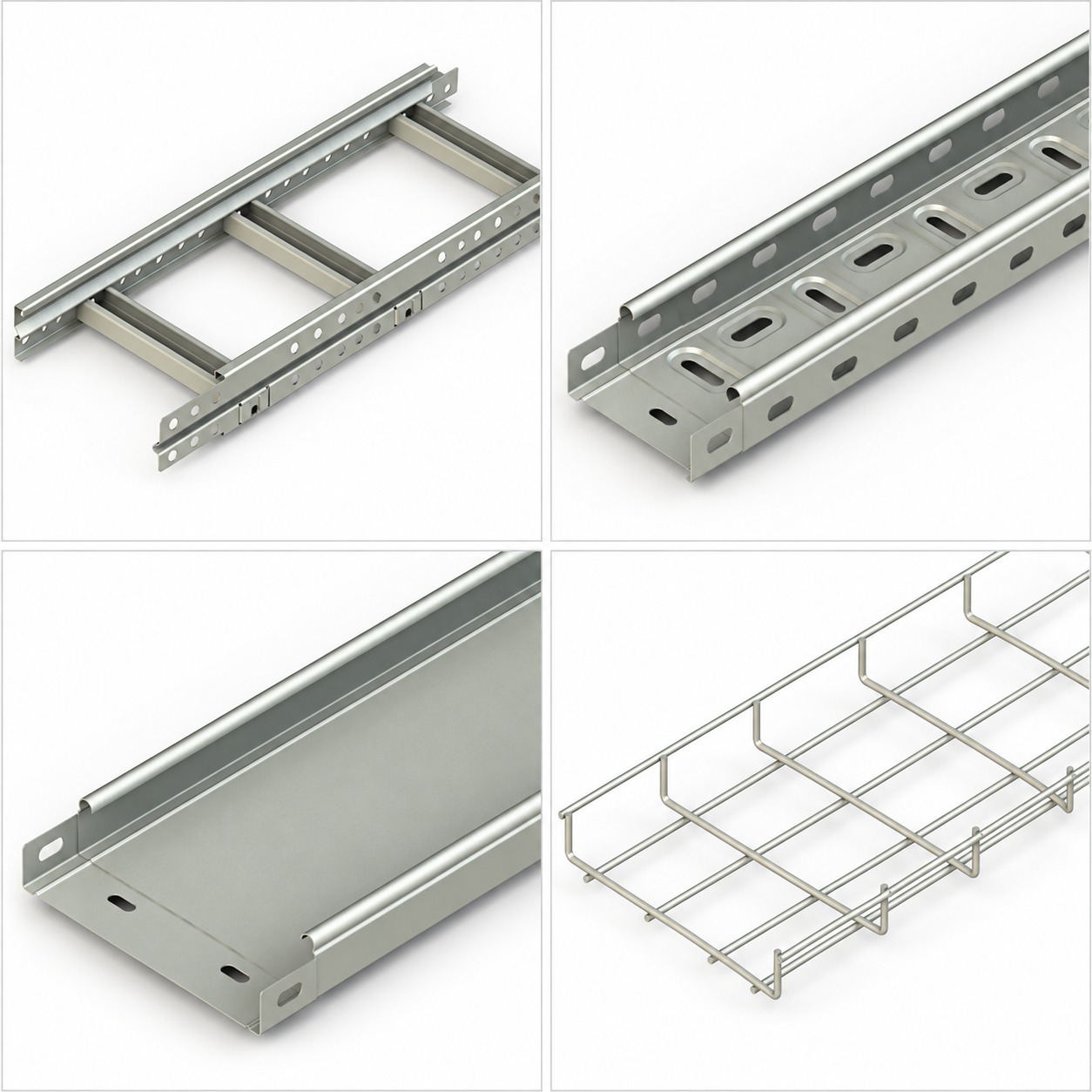
Use the cable trays overview and cable ladder overview as category navigation when discussing possible route forms. They are not evidence that a particular configuration suits this route.
Keep load units and test terms separate
Load language is where many industrial tray decisions become unsafe or ambiguous. Cable linear mass is mass per route length, commonly expressed as kg/m. To express that cable contribution as a force per length, use q = μ × g, where μ is linear mass and g is gravitational acceleration. The result is N/m. This conversion does not produce a total support reaction.
Tray self-weight is a separate distributed contribution. Distributed load describes force spread along a run, while a point load acts at a location. A support reaction depends on the actual support arrangement and load path. SWL, applied test load, failure load and deflection are also distinct terms. They must never be swapped or inferred from one another.
For each reviewed segment, state units, source, design condition and whether the value is a measured cable input, a calculated project action, a manufacturer declaration or a laboratory test result. Add fittings, covers, dividers, clamps, suspended services and temporary installation conditions only when their effect and configuration are documented. Do not compare a test result to a project demand until the tested arrangement, span, supports, accessories and boundary conditions are known.
The project team can use the load-capacity article as contextual reading, while keeping the exact calculation, acceptance basis and supporting documents in the project file.
Evaluate the full load unit and support arrangement
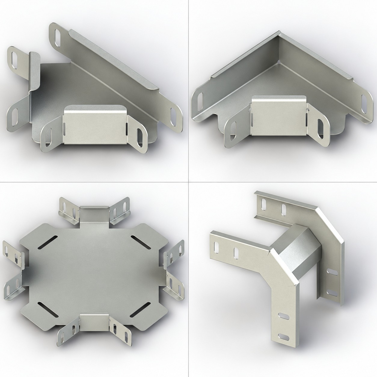
The review unit is not a side rail, a rung, or a catalog family in isolation. It is the full load unit: the exact tray or ladder type, width, side depth, material and finish; every relevant fitting; couplers and joint hardware; covers or dividers; cable restraint method; stated span; support type and location; and the connection to the supporting structure. A different accessory, joint position or support arrangement can change the question being evaluated.
Draw supports and joints on the same segment drawing. Identify whether a support sits near a fitting, whether a cable entry introduces a localized action, and whether maintenance may impose a temporary condition. Describe support hardware and attachment interfaces, but do not assume that containment documentation validates anchors, steelwork, concrete capacity, seismic actions or building structure. Those are separate design evidence streams.
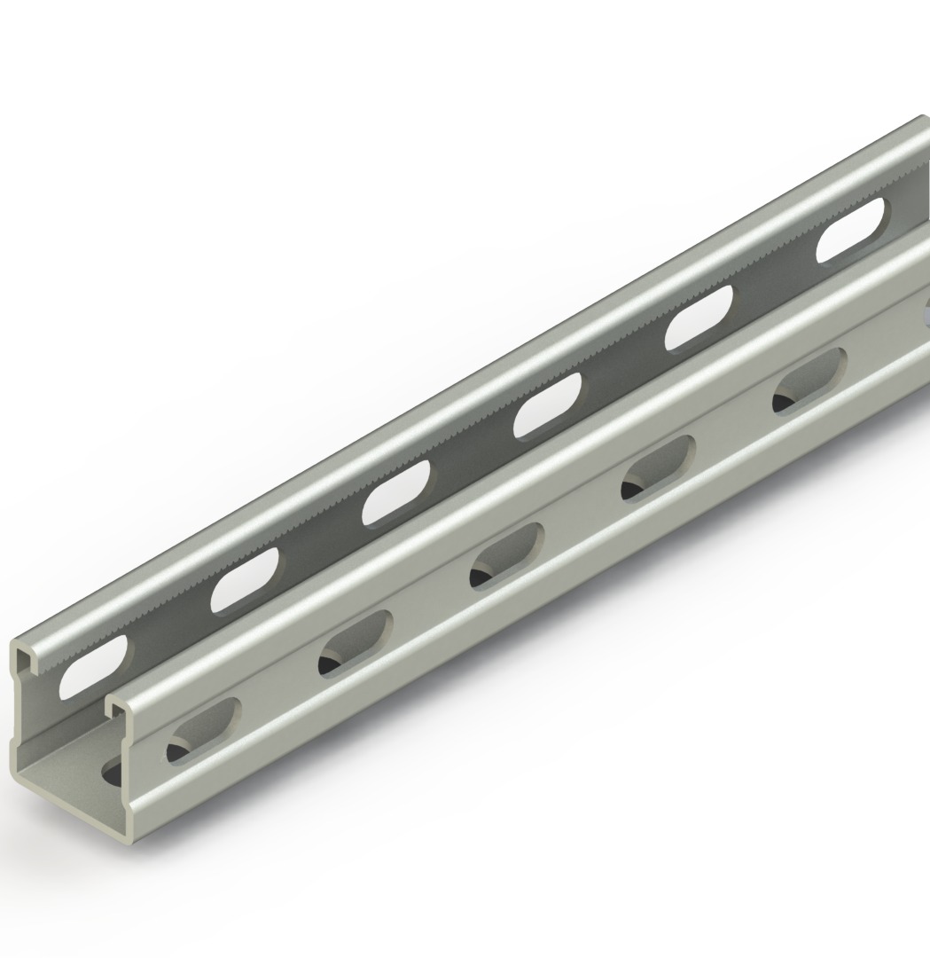
Coordinate early with the discipline responsible for the support system. The supporting systems page is useful for navigation, not proof of a support reaction, anchor capacity or project suitability. Require current project drawings and qualified structural review where the route depends on those interfaces.
Match test evidence to the exact configuration
Test evidence is useful only when its boundary is explicit. Request the edition and identity of the referenced standard, the manufacturer’s report or declaration, the specimen configuration, span, supports, fittings, joint position, load application, acceptance criterion, measured deflection and any stated limitations. Confirm whether the document covers a straight section, a fitting, a rung, a joint, a cover or a complete assembly.
A current manufacturer catalog can identify the components being considered, but it remains configuration documentation rather than a transferable field rating.[2] Use it to record the exact tray or ladder family, fittings, covers, joints and accessories under review. Do not treat a catalog category or a shared product name as permission to transfer a result between unrelated forms or assemblies.
Never translate a failure load into SWL, or an applied test load into a field capacity, without the governing method and explicit manufacturer documentation. Never extrapolate a result to an altered span, different support arrangement, new accessory, different material, corrosion condition or modified cable population. When evidence is incomplete, record the gap and return the item for clarification rather than filling it with a rule of thumb.
Treat environment and electrical duties as separate reviews
Industrial routes can be exposed to moisture, chemical contact, dust, washdown, outdoor weather, thermal cycling, vibration, impact or restricted access. These conditions should appear in a route exposure register with the responsible reviewer and required evidence. Material and finish selection follows that record, current manufacturer information and the project’s environmental assessment; no single material or finish is universally correct.
Cable containment also has limits. Cable ampacity belongs to electrical design and cable-manufacturer information. Bonding and earthing require their own verified design basis. Fire performance, penetration sealing, hazardous-area obligations, seismic actions and corrosion-life assessment each require their own applicable evidence. A tray selection package can identify interfaces and hold points, but it cannot certify those disciplines by implication.
At equipment transitions, verify physical clearances, cable bend constraints, protection against sharp edges, restraint requirements and access for inspection. Capture the reviewer’s resolution in the submittal rather than relying on a generic detail. This boundary-led approach makes omissions visible before installation.
Issue a traceable submittal and change-control plan
A release-ready submittal connects the route register to the exact configuration. Include route drawings; cable data and revision date; configuration schedule; support and joint layout; accessories; material and finish records; manufacturer installation information; test or declaration references; interface responsibilities; inspection points; and open deviations. Mark each document as project input, manufacturer evidence, calculation, test evidence or approval record.
Set hold points before purchase, before support installation, before cable pulling and before energization. At each hold point, compare field conditions with the released configuration. Check that changed cable schedules, late fittings, covers, added services, substitutions and support relocations are reviewed rather than silently absorbed.
Close the record with as-built route references, final cable schedule, product identification, approved deviations, inspection observations and maintenance-access notes. This creates a practical baseline for expansion and troubleshooting without claiming a future load, service life or performance outcome.
Inspect the route as an operating asset
Inspection should confirm the installed route against the released evidence, not merely look for visual damage. Review accessible supports, joints, fittings, cable restraint, covers, drainage or debris conditions, equipment transitions, labels and clearances. Compare the observed cable population and modifications with the controlled cable schedule. If a route has changed, reopen the relevant load, support, environmental and electrical reviews.
Maintenance teams also need safe access and a clear escalation path. Record who may authorize additions, which documents must be updated and when a qualified reviewer must reassess the route. This is especially important where abandoned cable, temporary work or operational changes can obscure the original assumptions.
Keep inspection findings factual: location, observed condition, drawing reference, date, reviewer and action owner. Avoid declaring capacity, compliance or suitability from inspection alone. An inspection can reveal a mismatch; it does not replace the documented evaluation of the full load unit.
Frequently Asked Questions
Short answers for a controlled industrial-route review.
It is a project-review label, not a universal rating. Define the route’s mechanical, environmental and operating conditions, then evaluate the documented configuration and evidence for that route.
Keep cable linear mass, tray self-weight, distributed load, point load, support reaction, SWL, applied test load, failure load and deflection distinct. A kg/m input becomes N/m only through q = μ × g; it is not a total support reaction.
No. A tray or ladder result has its own stated boundary. Anchors, steelwork, concrete, seismic actions and other structural interfaces require separate project evidence and qualified review.
No universal spacing is stated here. Use the actual span and support arrangement in the project evaluation, together with the exact configuration and current manufacturer documentation.
Record the change and compare it with the released route data, configuration and evidence. Reopen the affected reviews before treating the altered route as accepted.
Conclusion
Selecting an industrial heavy-duty route means defining the route rather than trusting a label. Keep load terms distinct, evaluate the full load unit, respect the limits of each test or declaration, and maintain separate evidence for structural, environmental and electrical duties. A controlled submittal and change record protect those decisions through installation and maintenance.
Discuss your project route requirements
Documented boundaries keep industrial cable routes reviewable as conditions change.