

Underfloor Trunking Design and Selection Guide
Good underfloor trunking design begins before a channel is selected. It coordinates cable routes with the floor assembly, service groups, access points, covers, device interfaces and handover records. This guide gives you a controlled way to define those decisions without claiming universal dimensions, ratings or layouts.
- Map the route and its floor interfaces.
- Document service segregation and access decisions.
- Keep structural, fire, moisture and electrical duties separate.
Table of Contents
Define the route before selecting a system
Underfloor trunking design starts with a route and coordination question, not a catalogue choice. The route may carry power, data, control or other services between distribution points, work areas and equipment. Its selection depends on the actual floor build-up, drawing interfaces, cable information, access needs and local project rules. A selected configuration should therefore be verified against the current drawings, the installed floor assembly, manufacturer data and installation instructions.
Begin with a simple route statement: where the route starts and ends, which zones it crosses, which services it is intended to accommodate, and which teams own adjacent work. Mark transitions to risers, floor boxes, device locations, equipment entries, expansion interfaces and penetrations. This turns a broad “underfloor” requirement into a set of visible coordination points.
BS EN 50085-2-2 describes particular requirements and tests for cable trunking and ducting systems intended for mounting underfloor, flushfloor or onfloor.[1] The standard’s published scope is useful for identifying the system category. It does not replace project design, local requirements, floor engineering or model-specific product evidence.
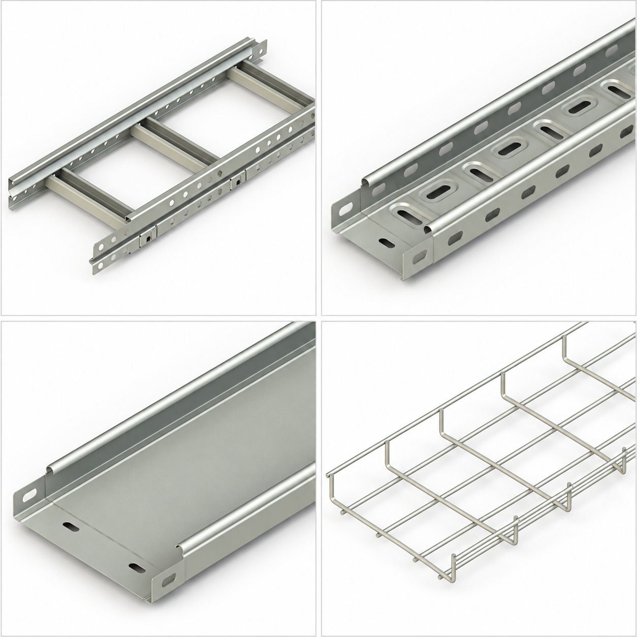
Use the underfloor trunking overview as category navigation while the project team gathers the applicable product documentation. The page does not prove that a particular configuration suits a floor, service mix or installation condition.
Coordinate the floor build-up and interfaces
An underfloor route is part of a floor assembly. Record the structural slab or deck, screed or raised-floor arrangement, finishes, movement interfaces, wet areas, penetrations and any zones reserved for other building services. Do not assume a universal floor depth, channel dimension, cover loading or embedded detail. Those characteristics depend on the actual system and the project’s structural and architectural design.
Coordinate early with architecture, structure, electrical design, interiors and the installer. Each discipline should be able to see where a route changes level, passes a doorway, approaches a floor opening, meets a service box or crosses a structural interface. A clash resolved on one drawing can still create an inaccessible cover, a compromised finish or an unbuildable transition if the floor detail is not reviewed as an assembly.
Use a drawing register rather than informal mark-ups. For each route segment, record its drawing reference, floor-zone reference, interface owner, planned access method and unresolved issue. Link the record to the latest revision. This makes late changes in furniture layouts, equipment positions or partitions easier to identify before installation.
The project team can compare the general trunking range during this stage. Keep category exploration separate from a technical acceptance decision for the exact arrangement.
Plan services and segregation as a documented decision
Underfloor trunking often serves more than one cable function, but a shared route does not automatically settle segregation. Identify every service group from the current cable schedule: its function, route constraints, termination points, installation sequence and any applicable separation or electromagnetic-compatibility requirements. Electrical protection, bonding and earthing are separate design duties and require their own verified basis.
Ask the responsible electrical and communications designers to state the required arrangement for the project. Then show how the proposed route, compartments, dividers, transitions and device boxes relate to that requirement. Do not prescribe a universal compartment layout, bend radius, fill percentage or cable quantity. Those values can change with cable construction, local rules, system documentation and the detailed route.
- Power services: identify supply path, protective-design interfaces and equipment entries.
- Data and control services: identify pathway constraints, terminations and any required separation evidence.
- Mixed-service points: show the device-box interface, service ownership and access sequence.
- Future changes: record a review path rather than promise that spare space will meet every later need.
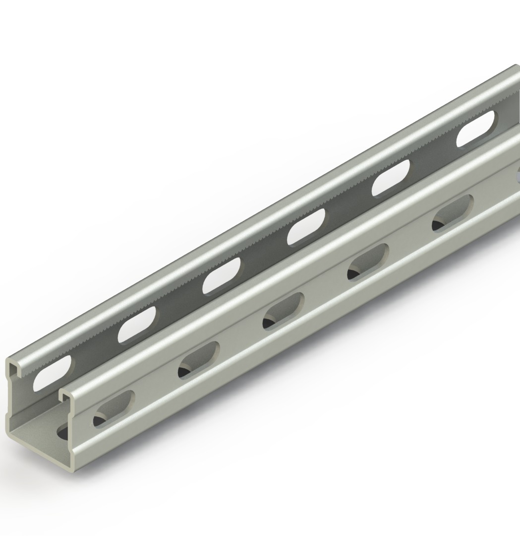
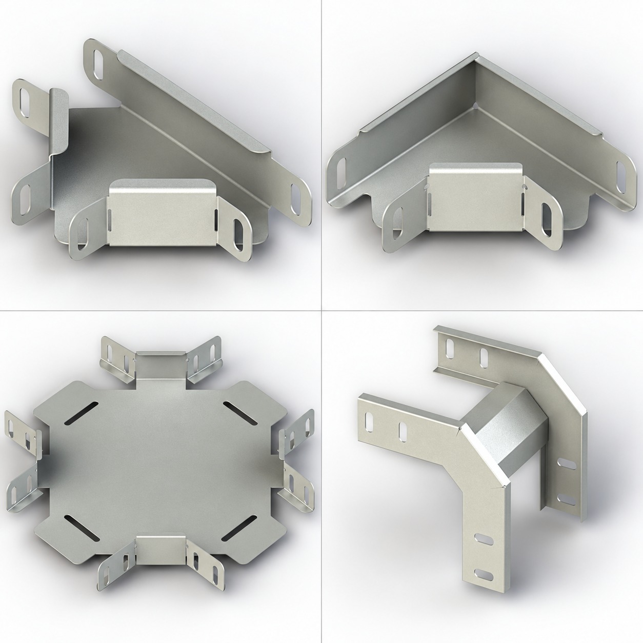
The trunking accessories page can help teams identify the kinds of fittings and interfaces that must be documented. It is not evidence for a required divider arrangement or compatibility with a named floor system.
Design access, covers and service points together
Access is a design input, not a maintenance afterthought. Locate planned inspection points, service boxes, removable covers, terminations and route transitions on the coordinated drawing. Consider how an installer reaches the work, how cables enter or leave the route, how a technician identifies a circuit and how finished surfaces will be reinstated. The correct access pattern is project-specific; do not convert this planning step into a universal access spacing or maintenance interval.
Covers and floor interfaces also need a stated purpose. A cover may be part of a route’s physical closure, finish coordination, access strategy or equipment interface, but its loading, moisture, fire, acoustic and electrical characteristics must be evaluated from the actual system evidence and project requirements. One property should not be inferred from another. A cover that appears robust is not automatically verified for every floor use, exposure or service condition.
At each service point, draw the relationship among trunking, cable exit, device or floor box, finish, furniture or equipment and the responsible trade. Confirm that the intended configuration can be installed and opened in the final room layout. Record any field adjustment as a controlled change rather than relying on a verbal agreement.
Separate environment, protection and compartmentation reviews
Underfloor routes can encounter cleaning water, spills, humidity, dust, temperature variation, vibration, impact, acoustic requirements or fire-resisting construction. Treat these as separate exposure and interface questions. A route may need review by the building-envelope, fire-stopping, acoustic, structural, electrical or facilities team, depending on where it runs. No generic underfloor statement can resolve all of those duties.
In particular, do not claim that a trunking route is waterproof, fire-rated, load-rated, EMC-rated or compatible with a floor system unless current model-specific evidence and project review support that conclusion. Fire and acoustic compartmentation involve the assembled floor and its penetrations. Moisture exposure involves the room use, cleaning method, drainage and interface details. Electrical protection and earthing involve the electrical design. Keep the evidence streams distinct.
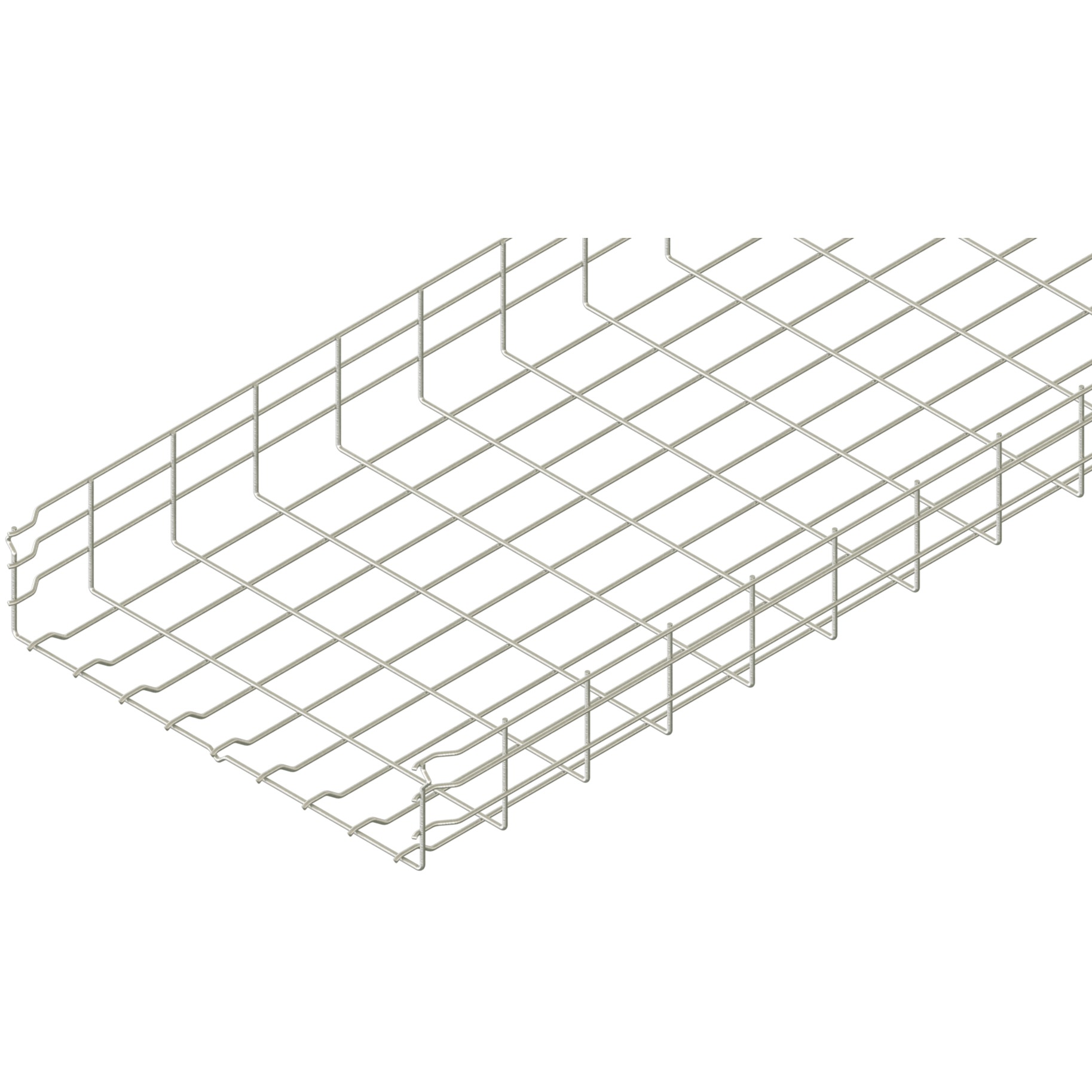
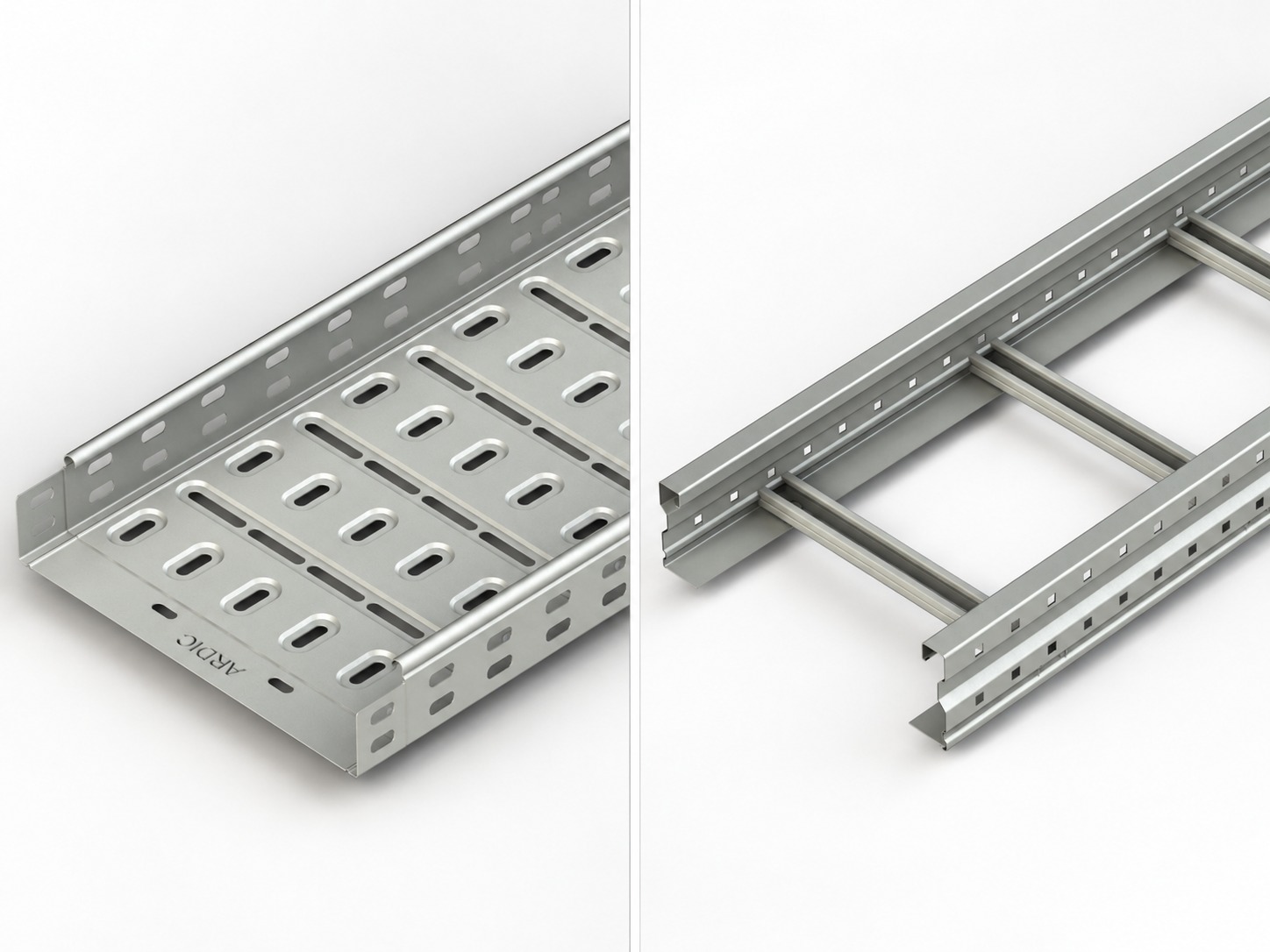
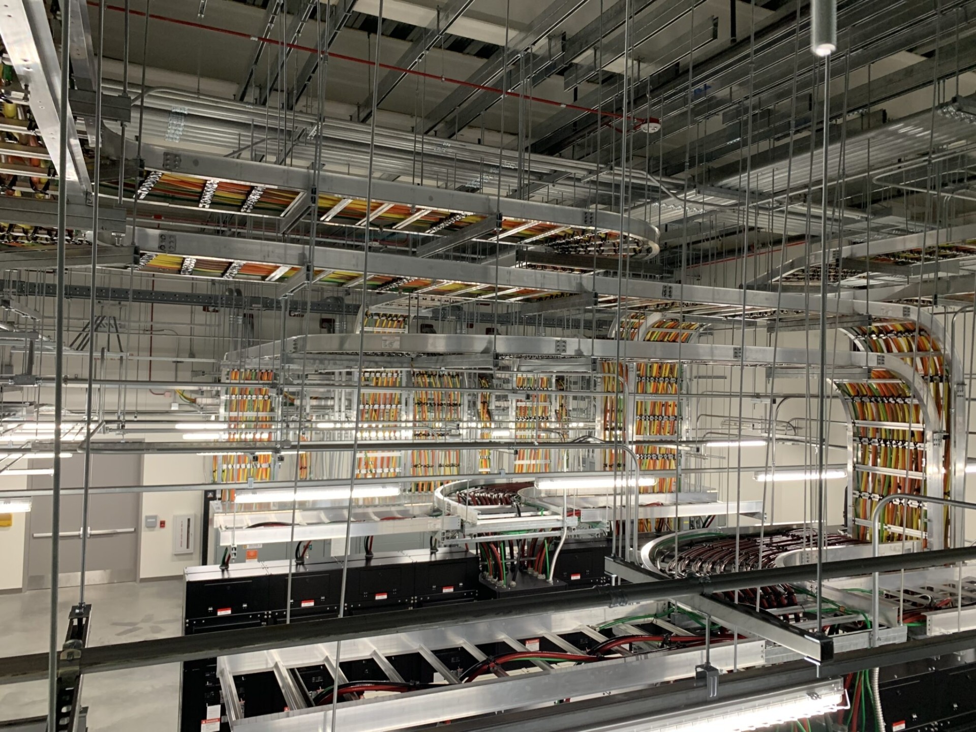
Where a route changes from underfloor trunking to another containment form, record the interface instead of assuming continuity. The cable trays overview is useful for identifying a separate category for discussion, but it does not confirm a transition, support, capacity or protective function. Bring the relevant manufacturers’ instructions and project drawings to the interface review.
Create a selection record that survives installation
A release-ready selection record connects each route segment to the information that was actually checked. Include the route drawing, floor-zone and build-up references, cable schedule revision, proposed configuration, accessories, device or service-box interfaces, current manufacturer documentation, installation instructions, applicable local requirements, review responsibilities and open items. Label whether an item is a project input, manufacturer document, design decision, inspection point or unresolved issue.
Before ordering or installation, run a short review: does the configuration match the latest floor detail? Are the intended service groups and transitions shown? Is access practical after finishes and furniture are in place? Have electrical protection, segregation, structural, fire, acoustic and moisture questions been sent to their responsible reviewers? If any answer is unclear, hold the affected route for clarification.
At handover, retain as-built route references, approved deviations, product identification, accessible service-point locations and the final cable schedule. This supports controlled maintenance and future modification without claiming a service life, capacity or universal expansion allowance.
Control changes through handover and future work
Underfloor routes are especially vulnerable to late coordination changes. A revised desk layout, extra outlet, relocated machine, altered partition or different cable can affect a route that already sits below finishes. Set review points before floor closure, before cable installation, before final finish work and before handover. At each point, compare the field condition with the released drawings and configuration record.
Use a short field-verification sheet at each review point. It can identify the route segment, drawing revision, installed fitting or service point, visible conflict, responsible party and required disposition. Photographing a condition may help the project record, but it does not replace the required technical evaluation. Where floor work has already obscured the route, rely on controlled as-built evidence and escalate uncertainty instead of making assumptions about the concealed configuration.
Make handover records usable for the people who will alter the space. Link each route reference to a room or zone, access-point locations and the approved record set. This avoids the common situation where a later fit-out team can see an outlet but cannot trace the constraints that apply below the finished floor.
Give facilities and fit-out teams a clear escalation path. They should know which route drawings and cable schedules must be updated, who can approve an alteration and which change requires renewed electrical, structural, fire, acoustic or manufacturer review. A useful record states observed facts—location, drawing reference, date, condition and action owner—rather than declaring compliance or performance from a visual check alone.
This disciplined approach makes future work more manageable. It does not promise that any arrangement will satisfy every new power, data, control, access or capacity request. It ensures that a proposed change is measured against the evidence and interfaces that made the original route reviewable.
Frequently Asked Questions
Short answers for an evidence-led underfloor route review.
It is a route and coordination system for cables and related service interfaces within, below or at floor level. The exact arrangement must be checked against the floor assembly, service requirements, local rules and current manufacturer information.
They are distinct containment categories and may have different intended applications, interfaces and documentation. A transition between them needs project-specific review; a category label alone does not establish compatibility or performance.
The required arrangement depends on the project’s electrical and communications design, applicable rules, cable information and the documented system configuration. Record the segregation decision rather than assuming a shared route is automatically acceptable.
Locate them through the coordinated route, room layout, service points, floor finish and maintenance plan. This guide does not prescribe universal access spacing; verify the arrangement with the project documents and installation instructions.
Compare the revision with the released route, service grouping, access plan, interfaces and manufacturer documentation. Reopen the affected reviews before accepting the altered configuration.
Conclusion
Underfloor trunking selection works best when the route, floor build-up, services, access points and interfaces are reviewed together. Keep segregation, electrical protection, structural support, moisture, fire and acoustic duties in their own evidence streams. Preserve the selected configuration and change record through installation and handover.
Discuss your underfloor trunking project
A documented route remains easier to review when the building changes.
Sources
- [1] BSI Knowledge: BS EN 50085-2-2:2008. Full URL and direct-retrieval record are retained in the package citation ledger.